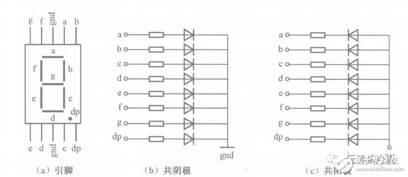
The inside of the digital tube is composed of seven strip-shaped light-emitting diodes and one small-dot light-emitting diode, and is combined into characters according to the brightness and darkness of each tube. Common digital tubes have 10 and pin. There are two common terminals, which can be divided into two types: common cathode and common anode according to the wiring form of the internal light-emitting diode. When in use, the common cathode digital tube is grounded at the common end, and the common anode digital tube is commonly connected to the power source. Refer to the figure below:

The digital tube can be controlled to be turned on and off by giving each pin a high level. Let's take an example. Take the common cathode digital tube as an example, let the digital tube display the number 0. As long as abcdef six pins input a high level, the digital tube can display the number 0.
There are two ways to work with LED displays: static display mode and dynamic display mode. The characteristic of static display is that each digital tube segment must be connected with an 8-bit data line to maintain the displayed glyph code. When a glyph code is sent once, the display glyph can be maintained until a new glyph code is sent. The feature of the dynamic display is that the segment selection lines of all the digital tubes are connected in parallel, and it is controlled by the bit selection line which one is valid. The bright digital tube adopts dynamic scanning display. The so-called dynamic scanning display sends the glyph codes and the corresponding bits to each of the digital tubes in turn, and uses the afterglow of the luminous tubes and the persistence of the human eye to make people feel like the digital tubes are simultaneously displayed. Through the above introduction, everyone should be aware of the basic principles of digital tube display. Let me look at some specific things below.
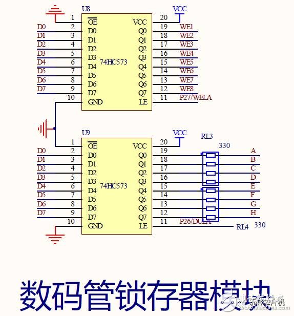
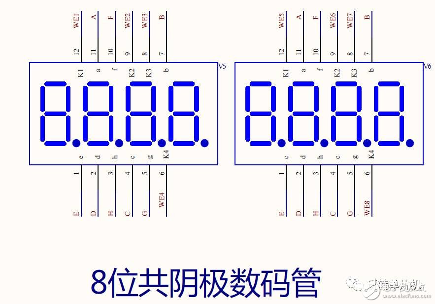
The following three diagrams are schematic diagrams of the development board. This development board uses two 74HC573 registers to reduce the use of the IO port of the microcontroller. The latch U8 is used to control the bit selection, that is, which digital tube is controlled. U9 control segment selection, that is, control what the digital tube displays. The digital tube and latch are connected to the P0 port of the microcontroller.


Next, look at the static display and dynamic display programs.
1, digital tube static display:
#include
#define uchar unsigned char
#define uint unsigned int
Sbit dula=P2^6; //Declare the latch end of the U9 latch
Sbit wela=P2^7; //Declare the latch end of the U8 latch
 Â
/* //Light up the first digital tube
Void main()
{
Wela=1; //Open the U8 latch
P0=0xfe; //Enter the bit selection signal
Wela=0; //turn off the U8 latch
    Â
Dula=1; //Open the U9 latch
P0 = 0x7f; / / send segment selection signal
Dula=0; //close the U8 latch
While(1);
} */
 Â
//eight digital tube loop display 0~F
Uchar code table[]={
0x3f, 0x06, 0x5b, 0x4f, 0x66, 0x6d, 0x7d, 0x07,
0x7f, 0x6f, 0x77, 0x7c, 0x39, 0x5e, 0x79, 0x71};
Uchar i;
Delay_ms(uint ms) { uint i,j; for(i=ms;i>0;i--) for(j=114;j>0;j--);}void main(){wela=1; P0=0x00;wela=0;while(1){for(i=0;i<16;i++){dula=1;P0=table[i];dula=0;delay_ms(500);}}}
2, dynamic digital tube #include
#define uint unsigned int
Sbit d=P2^6; sbit w=P2^7;
Delay_ms(uint ms)
{
Uint i,j;
For(i=ms;i>0;i--)
For(j=114;j>0;j--);
}
Uchar code table[]={0x3f,0x06,0x5b,0x4f,0x66,0x6d,0x7d,0x07,0x7f,0x6f,0x77,0x7c,0x39,0x5e,0x79,0x71 }; //eight digital tubes display 0~Funsigned Char code list[]={0xfe,0xfd,0xfb,0xf7,0xef,0xdf,0xbf,0x7f}; //The position of the digital tube is void main(){uchar i;while(1){for(i=0; i<8;i++){w=1;P0=list[i]; //Circle lights the i-th digital tube w=0;d=1;P0=table[i];d=0;delay500ms() ;} }}/* The code before program optimization w=1; P0=list[0]; //Light the first digit tube w=0; d=1; P0=table[0];d=0; Delay500ms();w=1;P0=list[1]; //Light up the second digit tube w=0;d=1;P0=table[1];d=0;delay500ms();w=1 ; P0 = list [2]; / / light up the third digital tube w = 0; d = 1; P0 = table [2]; d = 0; delay 500ms (); w = 1; P0 = list [3] ; //Light up the fourth digit tube w=0;d=1;P0=table[3];d=0;delay500ms();w=1;P0=list[4]; //light up fifth Bit digital tube w=0; d=1; P0=table[4]; d=0; delay500ms(); w=1; P0=list[5]; //lighting the sixth digit digital tube w=0; d=1; P0=table[5];d=0;delay500ms();w=1;P0=list[6]; //Light the seventh digit digital tube w=0;d=1;P0=table [6];d=0;delay500ms();w=1;P0=list[7]; //Light the eighth digit tube w=0;d=1;P0=table[7];d=0 ;delay500ms();*/
How about, through the above study, everyone should learn the basic principles of digital tube, then everyone can control the digital tube to display numbers and English letters.
Fume 2500 Disposable Device is one of the fume vapes besides fume extra and fume infinity. It's disposable, so no need to recharge and no need to maintain, Due to it's slime ultra can be easily to take to anywhere , it's very convenient and portable. When you want to vape, just open the fume ultra out of the pacakge box and puff it. The price of fume ultra is very cheap, welcome your inquiry to us!
Fume Ultra Vape,Fume Ultra Disposable,Fume Ultra Flavors,Fume Ultra Disposable Vape
Shenzhen Kate Technology Co., Ltd. , https://www.katevape.com
