RC sine wave oscillation circuit diagram: 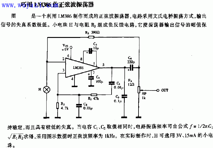
Two: RC sine wave oscillation circuit The common RC sine wave oscillation circuit is an RC series-parallel sine wave oscillation circuit, which is also called a Wen's bridge sine wave oscillation circuit. 
The series-parallel network is used here as a frequency selective and feedback network. Its circuit diagram is shown in Figure (1):
Its starting condition is: 
. Its oscillation frequency is: 
It is mainly used for low frequency oscillations. In order to generate a higher frequency sinusoidal signal, an LC sine wave oscillating circuit is generally used. Its oscillation frequency is: 
. The characteristic of the quartz oscillator is that its oscillation frequency is particularly stable, and it is often used in applications where the oscillation frequency is highly stable.
The following is also the RC sine wave circuit diagram:
An oscillating circuit composed of an RC frequency selective network is called an RC oscillating circuit, which is suitable for low frequency oscillation and is generally used to generate a low frequency signal of 1 Hz 1 MHz.
The commonly used RC oscillator circuit has RC bridge oscillator circuit and RC phase shift oscillator circuit. This section only focuses on the RC bridge oscillator circuit composed of series-parallel frequency selection network.
First, the frequency response of the RC network
The circuit of the RC series-parallel network is shown in the figure below. The impedance of the RC series arm is denoted by Z1.
The impedance of the RC parallel arm is indicated by Z2. Its frequency response is as follows: 

?? 
When R1=R2=R, C1=C2=C 
??
Amplitude and frequency characteristics:
: 
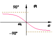
Phase frequency characteristics: ? 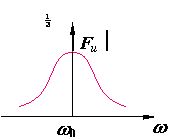

?
As can be seen from the above figure, when 
Time, 
Reach the maximum and equal 1/3, phase shift 
00, the output voltage is in phase with the input voltage, for which the output voltage is taken 
The amplitude is the largest, so the RC series-parallel network has the frequency selection effect.
Second, RC bridge type oscillation circuit (1) ? RC bridge type oscillation circuit
The RC bridge oscillator circuit is shown in the figure. The RC series-parallel network is connected to the output terminal of the operational amplifier and the non-inverting input terminal to form a positive feedback network with frequency selection. In addition, Rf and R1 are connected to the output of the operational amplifier and The phase input terminal forms a negative feedback amplification circuit together with the integrated operational amplifier.
As can be seen from the following figure, the positive feedback circuit and the negative feedback circuit form a Wien-bridge circuit. The input and output terminals of the operational amplifier are respectively connected across the diagonal of the bridge, so this oscillation circuit is called RC bridge. Oscillation circuit. 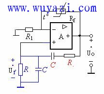
For the negative feedback amplifying circuit, the input signal is input from the non-inverting terminal (that is, the oscillating signal is input from this), and the negative feedback closed-loop voltage amplification factor can be obtained according to the virtual short and the virtual cut. 
When the frequency selective network is at f0???? 
???
Amplitude start condition: 
Phase start condition: 
(2) Stabilization process of RC Wen's bridge oscillating circuit
The amplitude stabilization of the RC bridge oscillator circuit is achieved by the thermistor Rf. Rf is a negative temperature coefficient thermistor. When the output voltage rises, the voltage applied to Rf rises, that is, the temperature rises, the resistance of Rf decreases, the negative feedback increases, and the output amplitude decreases, and vice versa. If the thermistor is a negative temperature coefficient, it should be placed at the position of R1.
1 If the circuit RF is a fixed resistor, the amplifier Au is a constant.
When starting up: it is required 
Oscillation balance: then required 
Only when the op amp enters the nonlinear working area can the gain fall to an equilibrium condition, resulting in severe distortion.
2 If the circuit RF is a negative temperature coefficient thermistor,
When starting up: Because the signal is weak, the thermistor RF is in a cold state, the resistance value is relatively large, and the Au value of the amplifier is large. 
?, the oscillation is established soon.
Oscillation balance: As the signal increases, the thermistor RF temperature rises, the resistance decreases, the amplifier Au value automatically drops, and the equilibrium condition is reached when the operational amplifier is also in the nonlinear working area. 
.
Example 7.1.1 shows the RC bridge oscillator circuit, R1=6.2K 
, Rp=22K 
, R3=4.3K 
R=8.2K 
, C=0.01
CWDM - Coarse Wavelength Division Multiplex
CCWDM is Compact CWDM (Compact Coarse Wavelength Division Multiplexing), a wavelength division multiplexing technology based on TFF (Thin Film Filter). It works in the same way as CWDM modules, except that CCWDM uses free space technology. , compared with the common CWDM optical fiber cascading method , the CCWDM package size is greatly reduced compared with CWDM modules, and the insertion loss is lower and the consistency is better; it can replace CWDM Products are used in telecommunications, enterprise networks, PON networks, cable television and other fields. The lower insertion loss enables the CCWDM module to have lower signal attenuation during use, thereby reducing the power requirements of the signal transmitter.
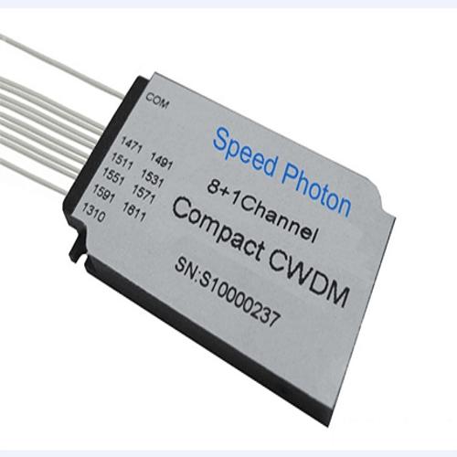
For the CWDM module, limited by the minimum bending radius of the optical fiber line, the size of the packaging box cannot be made too small, resulting in most of the space in the box being idle. The adjacent channels of CCWDM use parallel beams to cascade in free space instead of optical fibers. Without the optical fiber used for cascading, the size of the CCWDM packaging box can be greatly reduced. For example, the size of the common standard 4CH CWDM is 80×60×12 mm, and the size of the CCWDM module of Yiyuantong is 50×27×7.7mm, which is only 1/4 of the standard CWDM package size. Can be widely used in high-density environments.
Coarse Wdm Splitter,Wdm Splitter,Wdm Device
Shenzhen GL-COM Technology CO.,LTD. , https://www.szglcom.com
