Introduction
During the working process of the crane, due to the acceleration or deceleration of the operation of the trolley, the sway of the hoisting is often caused, which not only increases the difficulty of lifting and unloading, but also brings unsafe factors to the operation of the crane. Therefore, when the crane is working, the swing of the hoist must be controlled within a certain range, and the hoist should be immediately stopped when the destination is reached. To this end, various anti-shake measures have been proposed: such as the use of cross-wire rope anti-rolling device, separation car anti-rolling device, rocker beam anti-rolling device and other mechanical anti-shake system. Because the mechanical anti-shake is essentially the mechanical means to consume the swing energy to achieve the ultimate elimination of the swing, without considering the combination of anti-rolling and trolley operation control, the anti-rolling effect depends to a large extent on the operator's proficiency. The degree, and the anti-rolling effect of the crane under full load and no load are very different, it is difficult to meet the user's requirements. Later, the electronic anti-shake technology with visual sensor appeared, and the detected information was transmitted to the microcomputer in the control system through various sensors and detection components, and the optimal control parameters (such as PID control parameters) were processed by the internal control software of the microcomputer. Provided to the car speed control system, by adjusting the speed and direction of the car, controlling the operation of the car to reduce the swing amplitude of the spreader and load. However, since the current use is to install a launching device (laser transmitter, camera, etc.) and a receiving device on the small frame, a reflector is mounted on the spreader, and the spreader is swung back and forth when the spreader swings back and forth. Angle. Due to the need to install expensive visual sensor detection and receiving systems, the cost is very high; in the case of bad weather (such as dense fog, heavy rain, direct sunlight, etc.), the use of visual sensors is often With some limitations, it is difficult to get the best control.
In this paper, the mathematical model of crane load swing is established to clarify the relationship between hoisting swing and car running acceleration and deceleration, and the micro accelerometer based on micro-electromechanical system (MEMS) processing technology is applied to the anti-shake control system of crane. Instantly detect the running acceleration of the trolley and estimate the yaw angle of the hoist. By establishing a closed-loop control system, the car speed command is corrected according to the size of the hoisting swing to achieve anti-shake control. This method overcomes the shortcomings and defects of the traditional mechanical anti-shake technology and the electronic anti-shake technology with visual sensors to achieve the desired control effect.
Mathematical model of crane hoisting
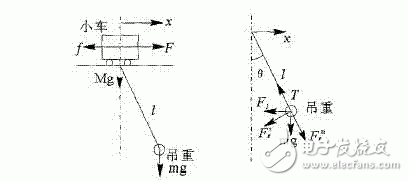
The simplified mechanical model analysis of the trolley-lifting sway system is shown in Figure 1(a). M and m are the mass of the trolley and the hoisting weight respectively, l is the length of the cable, x is the displacement of the trolley in the horizontal direction, θ is the swing angle of the hoisting weight, F is the running traction of the trolley, and f is the static resistance of the trolley running, g For gravity acceleration.
In order to facilitate the analysis, according to the basic situation of the crane work, here are some simplified treatments:
(1) Assume that the quality of the cable is negligible relative to the weight of the hoist and the quality of the trolley during the walking of the trolley;
(2) The hoisting weight and the hanger are regarded as the whole as the mass m for analysis;
(3) The hoisting weight and the wind and air damping of the cable during operation and the elastic deformation of the system are not counted.

(a) trolley - hoisting swing system (b) hoisting force balance
Fig.1 Mechanical model of trolley-lifting system
As shown in Fig. 1(b), let the tension of the cable be T, take x and θ as generalized coordinates, and establish a differential equation of motion for the car:
![]()
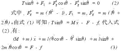
According to the D'Alembert principle, the force is analyzed for the hoisting weight, which is affected by the gravity mg, the cable tension T, the normal inertial force Fng, the tangential inertial force FÏ„g, and the horizontal inertial force F1. As shown in Figure 1 (b). Establish a balance equation in the horizontal direction, there is

Establish a balance equation perpendicular to the cable direction, with:
![]()
Finishing is available:
![]()
Then the linearization model of the spreader swing is:

If only a small θ change around the operating point θ0 is considered, and assuming that the length l of the cable is always constant throughout the process, the following simplification can be made:
![]()
This equation (6) is transformed into:

![]()
The other program (8) performs the Laplace transform, which has:
![]()
The object's transfer function is:
![]()
According to formula (8):

Equations (11) and (12) are solutions with initial conditions of t = 0, θ = 0, and θ = 0. It can be found that the swing of the spreader changes periodically with time, and the swing, swing speed and trolley running acceleration In direct proportion. Therefore, as long as the magnitude and direction of the acceleration of the trolley is determined, the swing and swing speed of the hoisting weight are determined accordingly.
Microelectromechanical systems (MEMS) and micro accelerometers
Microelectromechanical system (MEMS)
Since the 1960s, microelectronics and micromachining technologies (including silicon micromachining, silicon surface micromachining, LIGA, and wafer bonding) have combined to produce a variety of high performance, low cost, and miniaturized Sensors, actuators, drives, and microsystems. Microelectromechanical systems (MEMS) are micro-electromechanical systems that integrate micro-mechanisms, micro-sensors, micro-actuators, signal processing, control circuits, communication connections and power supplies. Such MEMS can not only acquire, process and transmit information or instructions, but also act autonomously or according to external instructions in accordance with the acquired information. At present, the most successful and widely used MEMS devices are micro-sensors. Micro-accelerometers, as outstanding representatives of micro-sensors, have been widely used in automotive intelligent control systems, such as airbag systems to detect and monitor front and rear collisions, etc. .
Structural model of micro accelerometer
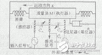
Figure 2 shows the structural model of a capacitive micro accelerometer.

Figure 2 Schematic diagram of the micro accelerometer
The mass in the figure is the actuator of the micro accelerometer, and the movable arm is connected to the mass; the fixed arm is opposite to the movable arm. The movable arm and the fixed arm form a capacitive structure as an inductor of the micro accelerometer. The spring is not a true spring, but a mechanical structure formed by the three-dimensional processing of silicon material, which acts as a spring in the accelerometer.
Hot Sale product ELF BAR TE5000,wholesale from factory.good quality and good taste.please contact us try our product.
If you want to know more about the products in Elf Bar, please click the product details to view parameters, models, pictures, prices and other information about Elf Bar TE5000.
Whatever you are a group or individual, we will do our best to provide you with accurate and comprehensive message about Elf Bar!
Elf bar TE5000, TE5000 Vape Pen, TE5000 Vape Device
Shenzhen Uscool Technology Co., Ltd , https://www.uscoolvape.com
