LED driver general requirements
The arrangement of the LEDs and the specification of the LED source determine the basic driver requirements. The main function of the LED driver is to limit the current flowing through the LED under certain operating conditions, regardless of the input and output voltages. The basic working circuit diagram of the LED driver is shown in Figure 1. The so-called "isolation" means that there is no physical electrical connection between the AC line voltage and the LED (ie, input and output). The most common is to use a transformer to electrically isolate. "Non-isolated" does not use high-frequency transformers for electrical isolation.

It is worth mentioning that in the LED lighting design, the AC-DC power conversion and constant current drive can be configured in different configurations:
(1) Integral configuration, that is, the two are fused together, all located in the lighting fixture, the advantages of this configuration include optimizing energy efficiency and simplifying installation;
(2) Distributed configuration, that is, the two exist separately, this configuration simplifies security considerations and increases flexibility.
How to choose LED driving method
Typical LED drivers on the market today include two types, linear drivers and switch drivers; the approximate range of application is shown in Figure 2. Switching regulators are used for high current applications with currents greater than 500 mA because linear actuators are limited to their own structural reasons. Provides such a large current; in low current applications with currents below 200mA, linear regulators or split regulators are typically used; in medium to 200mA to 500mA, linear regulators can be used. A switching regulator can be used.

Switching regulators are energy efficient and offer excellent brightness control. The linear regulator structure is simple, easy to design, provides steady current and overcurrent protection, and has no electromagnetic compatibility (EMC) problems.
In low-current LED applications, the resistive driver, although low in cost and simple in structure, has a low forward current under low voltage conditions, which causes LED brightness to be insufficient and under transient conditions such as load dump. The LED may be damaged; and the resistor is an energy consuming component, and the overall solution is less energy efficient, see Figure 3.

For example, in LED lighting applications using DC-DC power supplies, the LED driving methods that can be used are resistance type, linear regulators, and switching regulators. The basic application diagram is shown in Figure 4.

In the resistive drive mode, the forward current of the LED can be controlled by adjusting the current sense resistor in series with the LED. This drive mode is easy to design, low in cost, and has no electromagnetic compatibility (EMC) problem. The disadvantage is that it depends on the voltage and needs to be filtered. (binning) LED with low energy efficiency.
Linear regulators are also easy to design and have no EMC issues. They also support current regulation and fold back, and provide an external current set point. The power dissipation problem is insufficient, and the input voltage is always higher than the forward voltage. Voltage, and energy efficiency is not high. The switching regulator continuously controls the opening and closing of the switch (FET) through the PWM control module to control the flow of current.
Switching regulators have higher energy efficiency, are independent of voltage, and can control brightness. Insufficient is relatively high cost, high complexity, and electromagnetic interference (EMI) problems. Common topologies for LED DC-DC switching regulators include Buck, Boost, Buck-Boost, or Single-Ended Primary Inductor Converter (SEPIC).
Where the lowest input voltage under all operating conditions is greater than the maximum voltage of the LED string, a buck structure is used, such as driving 6 LEDs in series with 24 Vdc; in contrast, when the maximum input voltage is less than the minimum output voltage under all operating conditions Boost structure, such as 6 series LEDs driven by 12 Vdc; and the input voltage and output voltage range overlap can be buck-boost or SEPIC structure, such as 12 Vdc or 12 Vac to drive 4 series LEDs However, the cost and energy efficiency of this structure is the least desirable.
LED driver standard
The LED driver itself is also evolving, with a focus on further energy efficiency, increased functionality and power density. The US "Energy Star" solid-state lighting specification proposes energy efficiency limits at the lighting fixture level, involving specific product requirements including power factor. The requirements of the European Union's IEC 61347-2-13 (5/2006) standard for LED modules powered by DC or AC include:
Maximum safety extra low voltage (SELV) operating output voltage ≤ 25 Vrms (35.3 Vdc)
"appropriate" / safe work under different fault conditions
No smoke or flammable when it fails
In addition, the ANSI C82.xxx LED driver specification is still under development. In terms of safety, it is required to comply with UL, CSA and other standards, such as UL1310 (Class 2), UL 60950, UL1012. In addition, LED lighting design also involves product life cycle and reliability issues.
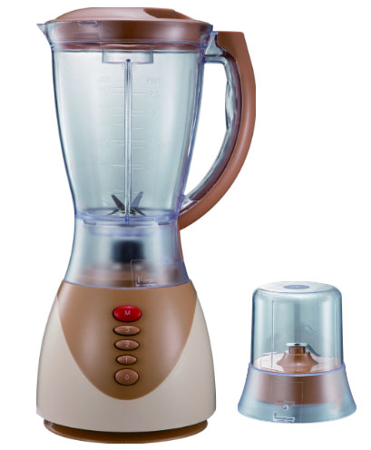
Push Button Food Blenders are another fashionable style blenders are popular with many countries. Except can with grinder, Push Button Food Blenders can with choppers and fliters.
Discription of Push Button Food Blenders
Size: 1.0L,1.25L, 1.5L, 1.6L
Housing: ABS, PP, Stainless steel
Speed: 2, 3, or 4 speeds with pulse
Packing: 6pcs/ctn

Push Button Food Blenders
Push Button Food Blenders,Push Button Blender,Push Button Hand Blender,Push Button Mini Blender
Flying Electronic Co., Ltd , https://www.flyingelectronic.com
