As with wireless remote car key (RKE) one kind of performance auto parts market and a product of the new car, by the people's favorite, which shows the first generation of RKE attractive to users. The installation rate of RKE systems in new vehicles in North America exceeds 80% , and in Europe more than 70% . Most of these systems use one-way ( simplex ) communication, but the second and third generation systems may provide a reply signal to the key, prompting the car to refuel or the tires need to be pumped up.
In addition to the convenience of users, the RKE system has other benefits: more car manufacturers around the world are using RKE- driven car braking technology in cars to minimize the rate of car theft. In Europe, auto manufacturing companies are cooperating with insurance companies to introduce this technology into cars, and insurance companies are using it as a condition to obtain auto insurance. This development trend has already appeared in Germany, and will expand to all Europe in recent years.
Briefly, the RKE system is integrated in a key fob RF transmitter (or key), the transmitter sends short bursts of data to the receiver in the car, and the receiver decodes the receiver controlled by the stopper of the door opening / turn off. The carrier frequency of the wireless link is 315MHz in the United States and Japan , and 433.92MHz (ISM band ) in Europe . In Japan, it is frequency shift keying (FSK) , but most countries in the world use amplitude shift keying (ASK) . The carrier is modulated between two levels of amplitude. In order to save power, the low level is usually close to zero, which constitutes a complete on-off key control (OOK) .

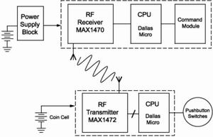
Picture 1 Â RKE system by circuitry (FIG bottom) on the key and car receiver circuit (FIG upper portion) composed of

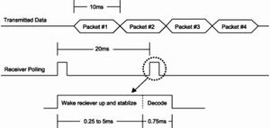
Picture 2 Â In order to monitor the key transmission, the RKE receiver must allocate time before decoding the input signal to wake up and stabilize it

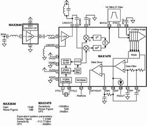
Figure 3 Adding an external LAN (MAX2640) can improve receiver sensitivity, but reduces the third- order intercept point
RKE details
A typical REK system ( Figure 1) includes a microcontroller in a key or key case. A push-button switch key in automobiles, and send wake mC 64 or 128-bit key data streams to RF transmitter, and the transmitter transmit the modulated carrier (PC board loop antenna manufacturing efficiency despite a simple printed circuit loop antenna Low, but inexpensive and widely used ) .
In a car, the RF receiver captures this data and sends it to another mC . This mC decodes and sends the appropriate information to start the engine or the car door. The multi-button key bag can select the driver's door or all the doors, or the trunk.
2.4Kbps between 20Kbps and transmit digital data stream typically includes a preamble, a command code, check digit and "rolling code" to ensure vehicle safety (otherwise the transmitted signal may occasionally open another car, or fall The thief's hand made it succeed ) .
There are several major factors that govern the design of the RKE system. Like all mass-produced components, the RKE system must have low cost and high reliability. The transmitter and receiver power should be kept to a minimum, because replacing the battery in the key is a hassle, and recharging the car battery is also a hassle. In response to these requirements, RKE system designers must skillfully handle receiver sensitivity, carrier tolerance, and other technical parameters in order to achieve the maximum transmission distance at low cost and minimum supply current.
Other constraints include local regulations for these short-range devices ( such as the US FCC regulations ) . The use of short-range devices does not require a license, but the product itself is subject to the laws and regulations of different countries. The relevant text in the United States is CFR ( Federal Regulatory Code ) , TItel47, Part15, which includes the 260 ~ 470MHz band (SecTIon15.231) and 902 ~ 928MHz band (SecTIon15.249) .
The following considers how the FCC specification affects the RKE design. SecTIon 15.231 specifies that the device transmits command or control signals, ID codes, and radio control signals during emergencies, but does not include video and audio, toy control signals, or continuous data. The transmission time cannot exceed 5 seconds. Only when the transmission rate is lower than once per hour, a transmission period of 1 second is allowed . The maximum field strength at a distance of 3 meters from the transmitting antenna is linearly proportional to the fundamental frequency (260 ~ 470MHz) , and its range is 3750mV / m ~ 12500mV / m . The bandwidth at the point 20dB lower than the carrier should not exceed 2.25% of the center frequency , and the spurious emission should be 20dB lower than the fundamental frequency .
The following is a detailed study of the issues related to the design of the RKE system. First, the carrier generation is studied.
Carrier generation
The first-generation RKE circuit includes a surface acoustic wave (SAW) device, which uses the SAW device to generate the RF carrier in the transmitter and the local oscillator (L0) frequency in the receiver . However, the starting frequency uncertainty of a typical SAW device is at least ± 100KHz , and the frequency stability with temperature change is quite poor. The IF bandwidth of the receiver is sufficient to allow carrier waves and excessive noise to enter, which in turn limits the response range of the car key transmitted signal.
Now replace the SAW device with a crystal-based phase-locked loop (PLL) . Although the cost of a crystal-based PLL transmitter is higher than that of a SAW resonator, its accuracy is 10 times higher than that of a SAW resonator . Therefore, the receiver can have a narrower IF bandwidth, thereby improving the signal-to-noise ratio and increasing the transmission distance.
The rated frequency of the earlier SAW devices was specified as the center frequency of the 433.05-434.79MHz band to ensure reliable operation within the expected operation and temperature range. Therefore, the rated carrier frequency for 433MHz applications is now 433.92MHz , so the PLL crystal must be selected accordingly .
The advanced receiver and transmitter chips integrate a PLL circuit, so you only need to connect a suitable crystal between the two pins of the chip. For example, the MAX1470PLL contains a divide-by- 64 unit and a low-end injected 10.7MHz IF ( this chip can work at 433.92MHz , but its image carrier suppression is optimal for 315MHz ) . The crystal frequency required for 315MHz operation is: fXTAL = (fRF-10.7) /64=4.7547MHz . The selected crystal should oscillate at 315MHz when presenting a 5pF capacitive load between the chip pins XTAL1 and XTAL2 . For how to adjust the crystal frequency, please refer to Application Note 1017 () .
Power saving
The battery life is very important in the RKE system. The system uses all methods to optimize the operating current and "on-time". The voltage controlled oscillator (VCO) in the receiver PLL has attracted much attention. The receiver must be constantly checked to avoid missing input requests to the car, and to stop as much as possible to save power, even during the short period between checks.
Typically, the key transmitter transmitting four consecutive 10ms data stream to ensure that the receiver can capture at least one of the data stream. The receiver needs to query every 20ms and jump to decode at least 2 data streams to ensure timing error and noise tolerance. It takes 0.75ms decoding time ( this is enough time for 7 or 8 -bit received data ) to determine whether the data is important.
In addition to the decoding time, the query operation must first "wake up" and stabilize the receiver circuit, which takes time. Most amplifier circuits can wake up quickly, but the VCO crystal is an electromechanical component that takes time to start vibration and requires more time to stabilize to the desired frequency. Generally, the superheterodyne receiver needs 2ms ~ 5ms to use for this kind of operation, but the MAX1470 only needs 0.25ms to perform this kind of operation ( only by adding enough power to maintain the oscillation of the crystal oscillator ) . Therefore, the MAX1470 checks the key transmission every 20ms , and it only takes 1ms (0.75ms decoding time plus 0.25ms stabilization time ) during the wake-up operation , see Figure 2 . Quick wake-up MAX1470 can use 3.3V instead of 5V , its net energy saving is 3 or 4 times ( compared to the general superheterodyne receiver ) , thereby extending battery life.
Strictly speaking, RKE is a short-distance technology ( for passive RKE systems, the distance is up to 20 meters or 1-2 meters ) , but ensuring low power and low-cost design in short transmission distances is a problem to be solved by RF circuits. For simplicity, the transmit and receive antennas are composed of copper wire loops or rectangular loops on a small printed circuit board. A simple LC network is used to match the impedance of the antenna and the transmit or receive chip ( see MAXIM 's application guide # 1830) .
Whether to add low noise amplifier
Low transmit power is limited by the uncertainty of FCC specifications, battery capacity, and transmit antenna positioning (which requires maximum sensitivity in the RKE receiver chip ) . One way to enhance receiver sensitivity is to add an external low-noise amplifier ( Figure 3) . However, the limitation of dynamic range makes this method unacceptable in applications. The following is an analysis based on the MAX1470 superheterodyne receiver.
The receiver sensitivity depends on the noise figure, the maximum signal-to-noise ratio required for carrier modulation detection and the thermal noise in the system:
S = NF + n0 + S / N Â Â Â Â Â Â Â Â Â Â Â Â Â Â Â Â Â Â Â Â Â Â Â Â Â Â Â Â Â Â (1)
Where S is the maximum value of the required signal level (dBm), NF is the noise figure of the receiver (dBm) , n0 is the receiver's thermal noise power (dBm), and S / N is the satisfaction detection ( usually based on acceptable error codes) Rate ) required output signal-to-noise ratio (dBm) .
For simplicity, according to Manchester encoded data, estimate S / N (5dBm) . According to the definition:
n0 = 10log10 (KTB / 1E-3)
Where K is the Boltzmann constant (1.38E-23), T is the absolute temperature in Kelvin, and B is the system noise bandwidth. At room temperature (T = 290 ° K) , 1 Hz bandwidth, n0 = -174dBm / Hz . In the 300KHz bandwidth, n0 = -119dBm .
Assuming that the system sensitivity (S) is -109dBm , calculated using Equation 1 , NF = 5dB . The relationship between noise figure (NF) and noise factor (F) is (NF) dB = 10logF, where F = 10 (NFdB / 10) . Therefore, F = 3.162 . For several two-port devices cascaded, the noise factor is:
FTotal = F1 + (F2-1) / G1 + (F3-1) / G1 × G2 + ...       (2)
Equation (2) can be used to calculate the new noise factor after adding an external low-noise amplifier (LAN) to the system . For the MAX2640LAN , NF = 1dB and gain = 15dB ( ie F1 = 1.26 , G1 = 31.62) . The original system noise factor is 3.162 , so, FTotal = 1.327 , where F1 is 1.23dB , substituted into equation 1 , we get:
S = 1.23-119 + 5 = -112.77dB
Assuming that the original system sensitivity is -119dB, only 3.77dB is obtained in this part . In addition, the virtual range is also paid attention to, which is represented by the third- order intercept point (IIP3) . For a total IIP3 of -34dBm , the MAX1470 has an internal 16dBm gain and an internal mixer of -18dBmIIP3 . Adding an external LAN with 15dB gain reduces it to -49 dBm . Therefore, adding an external LAN improves the sensitivity by 4 dB, but reduces the system dynamic range by 15 dB . For a given application, it is necessary to decide whether to accept an external LAN in consideration of this compromise .
prediction
The next development of the RKE system is two-way ( half-duplex ) communication, of which the first "passive RKE " has appeared in some high-end cars. You can simply wake up the car with the key in your pocket, and check your arrival continuously through the transmitter. When you are within the valid range (1 meter or 2 meters ) , the key establishes two-way communication with the car and opens the door for you. The current two-way system includes a useful answering function Industrial Panel Pc
Industrial Touch Panel,Panel Mount Computer,Industrial Panel Pc,Industrial Touch Panel Pc
Shenzhen Hengstar Technology Co., Ltd. , https://www.angeltondal.com
