Intelligent model car chassis technology
Abstract: This paper introduces the principles of steering wheel positioning parameters, the selection of the center of gravity of the vehicle, and side slip from the perspective of automobile theory for the model car chassis for smart car competition, and through the steering wheel positioning parameters, steering gear performance and model car Turning to the steady state test, the influence law between these adjustment parameters is obtained, which can provide a certain reference for the relevant participating teams in algorithm formulation, simulation parameter setting, and hardware structure adjustment and optimization of chassis and steering gear.
Keywords: front wheel positioning; steering gear; steering; turning radius
introduction
This article introduces the principles of steering wheel positioning, the selection of the center of gravity of the vehicle, and side slip from the perspective of automobile theory, and conducts a series of tests on the chassis of the model car for competition, including the selection of steering wheel positioning parameters, steering gear performance test and model Steady-state testing of the car's steering resulted in the rules of the influence of these adjustment parameters, hoping to provide some reference for the relevant teams in the formulation of algorithms, simulation parameter settings, and the adjustment and optimization of hardware structures such as chassis and steering gear.
Car chassis related performance
Steering wheel positioning parameters
For a car, to maintain the stability of the straight-line driving of the vehicle so that it automatically turns to turn and the steering is light, the wheel positioning parameters must be determined, including the kingpin tilt, the kingpin camber, the front wheel camber, and the front wheel toe.
Kingpin angle
The caster angle of the kingpin forms a positive torque after the wheel deflects, hindering the wheel deflection. The larger the caster angle of the kingpin, the higher the vehicle speed, and the stronger the automatic return force after the wheel deflects. However, if the return torque is too large, it will cause the front wheel return to be too sharp, accelerate the front wheel swing, and make the steering heavy. Generally, the backward tilt angle is 1 ° to 3 °.
Kingpin inclination
In the front-rear direction of the car, the kingpin tilts inward at an angle, and the angle between the kingpin axis and the vertical line is called the kingpin inclination angle. When the steering wheel of the car is deflected under the action of external force, due to the inclination of the kingpin, the wheel and the front of the entire car will be lifted to a certain height. After the external force disappears, the wheel will try to return to the original middle under the action of gravity position. Usually the kingpin inclination angle is not more than 8 °.
Camber of front wheel
In the lateral plane of the car, the center plane of the front wheels inclines outward at an angle called the camber angle of the front wheels. On the one hand, the camber angle of the front wheels can make the wheels roll near the vertical road surface and slide to reduce the steering resistance and make the car turn lighter; on the other hand, the load of the bearing and the lock nut is reduced, the service life is increased, and the safety is improved. Generally, the camber angle of the front wheel is about 1 °, but for vehicles with high speed and sharp steering requirements, the camber angle of the front wheel can be reduced or even negative.
Front toe
Looking down on the wheels, the planes of rotation of the two front wheels of the car are not completely parallel, but with a slight angle. This phenomenon is called the front wheel toe. The function of the front toe of the wheel is to reduce or eliminate the adverse consequences caused by the camber of the front wheel. The two coordinate with each other to ensure that the front wheel rolls without slipping while the car is running. The front toe is generally 0-12mm. However, the camber angle of the front wheels of modern cars tends to be reduced or even negative, and the front toe of the front wheels should also be reduced or even negative.
Influence of center of gravity position on vehicle performance
The position of the center of gravity of the car is usually expressed by the horizontal distance of the center of gravity from the centerline of the front axle and the height of the center of gravity from the horizontal road surface. The position of the center of gravity can be measured by experimental methods and estimation methods.
Impact on dynamic performance
The normal driving of the car must meet the driving-attachment conditions:
That is, the driving force of the car must be greater than or equal to the sum of the slope resistance, rolling resistance, and air resistance and equal to the adhesion of the driving wheel of the car. The adhesion is related to the road surface adhesion coefficient and the axial load of the drive shaft, and the axial load of the drive shaft depends on the horizontal position of the center of gravity. Therefore, the position of the center of gravity must ensure that the drive wheels can provide sufficient adhesion. From this point of view only, the closer the center of gravity is to the drive shaft, the better.
Impact on braking performance
The braking performance of the car requires a large braking deceleration, a short braking distance, and good stability in the braking direction, that is, the loss of steering of the front wheels, the slip of the rear wheels and the deviation of the wheels are not easy to occur. The stability of the braking direction is related to the order of locking of the front and rear wheels, and the order of locking is related to the position of the center of gravity. If the position of the center of gravity ensures the synchronous adhesion coefficient of the car (β is the ratio of the front braking force to the braking force of the vehicle, b is The horizontal distance from the center of gravity to the rear axle) is equal to the adhesion coefficient of the common road surface of the car, and the braking stability is better; if the center of gravity moves forward, b increases, the rear axle slips easily, which is dangerous to high-speed vehicles; if the center of gravity moves backward , B decreases, the front wheels tend to lose their steering ability.
Impact on passability
When the car is driving on a steep side slope or a high-speed sharp turn, it will overturn sideways. To avoid this danger, the center of gravity should be reduced as much as possible while ensuring a minimum ground clearance.
Based on the above analysis, after installing many circuit boards, the vertical position of the center of gravity of the model car should be as low as possible, and the horizontal position should be close to the rear axle on the center line of the car.
Car skid
In order to ensure the straight rolling of the steering wheel of the car without lateral slip, it is required that the camber angle of the wheel and the toe of the wheel be properly matched. When the value of the toe of the wheel and the camber of the wheel are not properly matched, the wheel may not roll purely during straight travel. The side slip phenomenon occurs. When this slippage phenomenon is too serious, it will destroy the attachment conditions of the wheels and make the car lose its ability to orientate. The sideslip is divided into the following situations.
Directional sliding
Random side slip
Steering slip
Brake skid
During braking, if the front wheels lock and drag first, then side slipping may occur.
Some compensation measures can be taken to reduce side slip. For directional sideslip, it is the basic means to compensate the type W side slip caused by camber with the type Q side slip generated by the front wheel toe. The nature of the Q-type side slip is: the size of the side slip is equal to the size of the toe angle; the direction of the side slip is opposite to the direction of the toe angle, and is related to the direction of the vehicle's travel; it is not related to the quality of the road surface. For random side slip, mainly from changing the independent suspension structure, such as the double-wishbone independent suspension axle wheel of this model, the random side slip can use the four-bar linkage theory to change the length of the upper and lower cross arms to make the model travel. During the process, the wheel track does not change much, thereby reducing random side slip. For steering sideslip, it is mainly by choosing the appropriate kingpin angle, and reasonably matching the kingpin inclination and caster angle, as far as possible to cause camber or increase camber of the steering inner wheel, so that the steering outer wheel produces camber or reduce camber.
Model car chassis performance
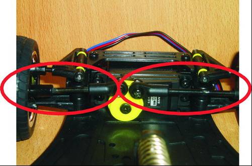
The chassis of the model car uses an equal-length double-wishbone independent suspension (see Figure 1). When the wheels jump up and down, the wheel plane is not inclined, but the wheelbase will change greatly, so the wheels may slip sideways. Sexuality is greater. There are 6 parameters adjustable in this car, among which the inclination angle of the kingpin has little effect on the performance of the model car and can be set.

Figure 1 Front wheel toe adjustment
Kingpin angle
The back tilt angle of the kingpin can be increased by increasing the number of shims. There are 4 shims in total, front 2 back 2, back tilt angle 0; front 1 back 3, back tilt angle; front 0 back 4, back tilt angle.
For this model car, if you want to make the steering flexible, the caster angle of the kingpin is optional; if you want to increase the return torque, the caster angle is optional.
Camber of front wheel
It has a greater relationship with the side slip of the model car and needs to match the front toe of the front wheel, which can be set.
Front toe
The front wheels are steered by the steering gear driving the left and right tie rods. After the position of the kingpin in the vertical direction is determined, the size of the front wheel toe can be changed by changing the length of the left and right tie rods. The left lever is short and the adjustable range is 10.8mm to 18.1mm; the right lever is long and the adjustable range is 29.2mm to 37.6mm (as shown in the red circle in Figure 1).
Chassis ground clearance
The ground clearance of the front half of the chassis can be adjusted between the lower suspension arm of the independent suspension and the bottom plate by adding or removing spacers. The spacers are available in 1mm and 2mm specifications. A piece of gasket is not added, and the ground clearance at the front of the vehicle is 9 mm, so the adjustment range of the ground clearance is 9 mm to 12 mm. From the existing experience, after installing the sensor, if the distance is too small, it will reduce the passing rate of the model car when climbing; if it is too large, it will affect the sensitivity of the sensor.
Pre-tensioning of longitudinal shock absorber spring in rear suspension
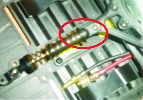
Adding a gasket at the red circle in Fig. 2 can increase the spring preload.

Figure 2 Adjustment of suspension preload
Servo performance test
Connect a varistor to the shaft of the steering gear. The varistor has three connectors. The two ends of the varistor are connected to the 5V power supply and the other end is grounded. The middle connector is connected to the oscilloscope. The oscilloscope measures the voltage. When the steering gear drives the front wheel to rotate, the resistance of the rheostat changes accordingly, and the voltage value of the oscilloscope also changes. That is, the voltage corresponds to the steering angle of the steering gear. In this way, the steering angle can be known by measuring the change of the voltage with time. Rate of change. It can be seen from the test that the steering gear rotates from the maximum rotation angle on one side to the maximum rotation angle on the other side at approximately uniform speed. Combined with the measurement of the maximum rotation angle of the front wheel, it can be estimated that the speed of the steering gear is about 2.42rad / s-2.52rad / s. According to the relevant knowledge of automobile theory, the performance of the steering gear is relatively soft, and it can be adjusted by increasing the front toe of the front wheel.
The test of the performance of the steering gear is mainly used to set the simulation parameters. At the same time, the estimated rotation speed of the steering gear also has a certain reference significance to the corresponding speed of the program and the speed limit of the vehicle when turning.
Model car steady-state steering test
This section discusses the relationship between the PWM duty cycle of the steering gear and the vehicle speed and turning radius. In the test, the PWM duty cycle of the servo is set to 6 gears, which are expressed as 1, 2, 3, 4, 5, 6 respectively. The larger the number, the greater the rotation angle. As shown in Figure 1, the steering speed corresponds to the speed of the gear 1-turning radius corresponding map, it can be seen from the test, under the same turning angle, the turning radius and the vehicle speed are roughly linear.
According to the relevant data of the model car, the theoretical turning radius is 275mm. This value is close to the turning radius at 0.31m / s in the model car test; when the model car speed is greater than 1.4m / s, the sideslip phenomenon begins to appear.
Conclusion
Through theoretical analysis and experimental testing, this paper analyzes the adjustment of steering wheel positioning parameters, selection of key points, control of side slip, adjustment of chassis height, steering performance and steering stability of the model car for smart car competition. Suggestions for adjusting the relevant parameters of the model car are given. Since the steering parameters of the above model cars affect each other, this article only provides the adjustment trend of each parameter, and the best matching value needs to be obtained according to the track debugging.
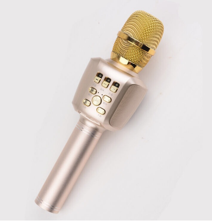
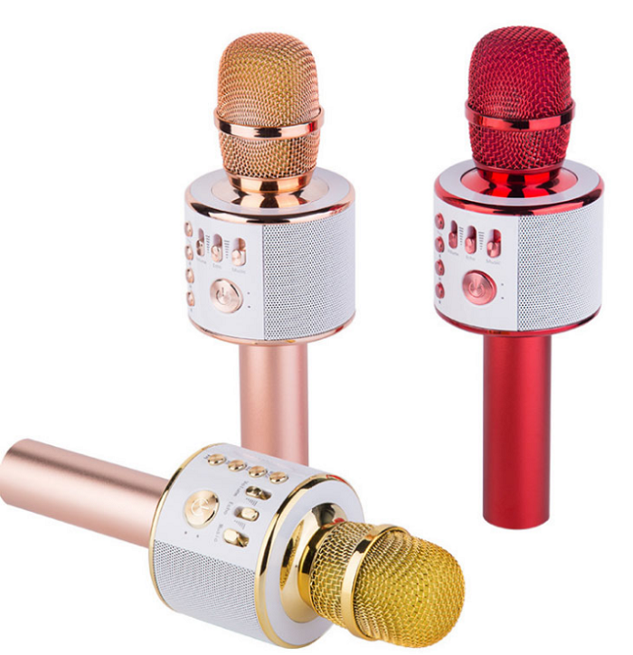
This Bluetooth Karaoke Microphone Speaker is designed for music singing fans. This Karaoke Microphone Speaker is the most wonderful microphone. This portable Microphone speaker combines microphone, KTV echo and louder speaker in one. The Good Speakerphone for Home Office connects Mobile phone/tablet/computer by Bluetooth easily, you can enjoy singing at anywhere and anytime. With cable, it supports singing recording at the same time. At home party, this Portable Karaoke Speaker can increase the enjoyment of life, you can sing song freely with your family and friends, and you can use this Wireless Microphone systems record your songs and submit to some sing APP to get high popularity. Also people can use this Bluetooth Conference Speakerphone make speech practice to add your public presentation ability. It is a good present for your family and friends.


Microphone Speaker
Microphone Speaker,Portable Mic System,Portable Mic Speaker System,Portable Wireless Mic System
Shenzhen New Wonderful Technology Co., Ltd. , https://www.sznewwonderful.com
