DeviceNet is an open communication network based on CAN bus technology and in line with global industry standards. The equipment-level network located in industrial control not only reduces the complexity of the system, but also reduces the cable hardware wiring of equipment communication, improves system reliability, and reduces installation and maintenance costs. It is an ideal solution for distributed control systems.
The DeviceNet specification defines a network communication standard in which data can be communicated between devices that make up an industrial control system. In addition to providing an application layer definition for the ISO model, the DeviceNet specification defines some physical layers and data link layers. Not only the physical connection of the DeviceNet node is specified in the specification, but also the connector, cable type, length, and communication-related indicators, switches, and related indoor nameplates.
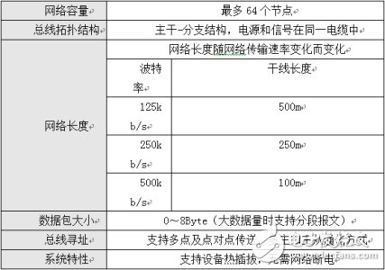
1. Basic Concept of DeviceNetBased on the CAN protocol, DeviceNet follows the physical layer and data link layer defined by the CAN protocol, and supplements different packet formats, bus access arbitration rules, and fault detection and isolation methods. The functions and features of DeviceNet are shown in Table 1.
Table 1 DeviceNet Features
DeviceNet's application layer protocol uses the Common Industrial Protocol (CIP). CIP is a strictly object-oriented protocol at a high level. Each CIP object has attributes (data), services (commands), connections, and behaviors (the relationship between attribute values ​​and services). Its main functions are two: one is connection-oriented communication; the other is to define standard industrial applications. Object. The communication section is described in detail below.
The most important feature of CIP communication is that it transmits different types of packets in different ways. According to the packet quality requirements, the packets to be sent are classified into explicit packets and implicit packets.
Another important feature of CIP is that communications are connection based. Therefore, any two nodes on the DeviceNet network must establish a connection before communication, and the connection can be dynamically established and revoked. Please note that the "connection" here is a logical relationship, not a physical layer connection.
DeviceNet supports two types of connections: explicit information connections and I/O connections.
The explicit information connection is a point-to-point connection. The receiver of the message must respond to the received message. Usually, the time of the message is not high. It is mainly used to upload/download programs, modify device parameters, and trend. Analysis and diagnosis, etc.
The I/O connection is used to transmit I/O messages with high real-time requirements, and can be transmitted one-to-one and one-to-many. DeviceNet supports multiple I/O data triggering methods, such as Bit strobe, Poll, COS: Change Of State/Cyclic.
Bit strobe: Using 8-byte broadcast messages, each bit corresponds to 64 nodes on the network, specifying the slave node that requires the response, and the response message is up to 8 bytes.
Polling: This triggering method is suitable for most devices. The polling command can transfer any amount of data compared to the small amount of I/O data of the bit strobe. The polling command is sent to each slave device in turn, and the slave responds after receiving the command.
State change: This mode is mostly used for discrete devices. When the device state changes, the event trigger mode is used to generate communication instead of relying on the master device to continuously query. To prevent the device from being dropped, the heartbeat packet is added and the running status of the device is obtained periodically.
Cycle: Applicable to some analog devices. It can set the time interval of cyclic communication flexibly according to the speed of the device signal. It can reduce unnecessary network traffic. The cycle time setting value should be less than the time value of the analog input change. In each device, loops and state changes are mutually exclusive, and only one connection can be used at a time.
The general flow of establishing communication between two devices in a DeviceNet network is described below with reference to FIG.
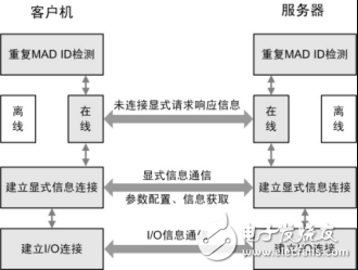
Figure 1 Basic process of DeviceNet communication
There are up to 64 nodes on the DeviceNet network, and the node address (MAC ID) can be 0~63. Each node has a unique MAC ID. Therefore, each node must perform repeated MAC ID detection after power-on and before going online to confirm whether its MAC ID has been used by other nodes on the network. After the node is powered on, it will send duplicate MAC ID detection packets at intervals of one second. If two consecutive transmissions do not receive duplicate MAC ID response packets from other nodes, the node can use this MAC ID and convert to Online status, otherwise the MAC ID is already occupied by other nodes, and the node is offline. Then, the explicit information connection is established by not connecting the explicit information, and the master and slave stations perform various configurations and information exchanges through the explicit information, and the master station reads the identification information of the slave station through the explicit information, and the configuration information saved in advance. For comparison, the master will perform the next operation on the slave only if it is completely consistent, otherwise the master will actively release the explicit information connection. Finally, I/O connections are established and real-time data is sent and received via I/O connections.
Note: The process of establishing I/O connections by different master modules is different. The above emphasizes that the DeviceNet network is a communication network based on connection.
DeviceNet is a connection-based network system. A DeviceNet connection provides a path between multiple applications. When a connection is established, a connection-related transfer is assigned a connection ID CID. If the connection contains a two-way exchange then two connection ID values ​​should be assigned. figure 2.

Figure 2 Connection and connection ID
2.DeviceNet About the use of the CAN identification areaThe valid 11-bit CAN flag on DeviceNet is divided into 4 separate packet groups 1 group 2 and group 3 and group 4.

Figure 3 DeviceNet CAN message definition
Message ID: identifies an information information ID in a group of information within a particular endpoint such that when a multi-connection connection can be established in a single group of information within a particular endpoint, the endpoint is generated using a combination of the information ID and the MAC ID. A connection ID The connection ID specifies the specific details in the CAN identification area associated with the corresponding transmission. It will be described in subsequent sections of this specification. Note that Group 2 and Group 3 predefine the use of the Definitive Information ID;
Source MAC ID: This MAC ID is assigned to the sending node groups 1 and 3 and needs to specify the source MAC ID in the CAN identification area;
Destination MAC ID (DesTInaTIon MAC ID): This MAC ID is assigned to the Receive Device Group 2 to allow the source or destination MAC ID to be specified in the MAC ID portion of the CAN Identity Area.
3. Information group 1DeviceNet does not predefine group 1 information ID usage group 1 information ID describes various group 1 information exchanged through a special endpoint.
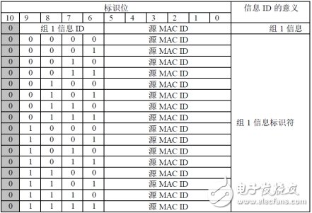
Figure 4 DeviceNet Information Group 1 Definition
In the transmission of group 1, the bus access priority is evenly distributed to all devices on the network. When two or more group 1 information is used for CAN bus access arbitration, the information of the small number group 1 information ID value will win the arbitration and obtain the bus. Access rights. For example, device #20 message_ID = 2 will win the arbitration before device #5 message_ID = 6.
If two or more Group 1 messages with equal information ID values ​​are bus arbitrated then the transmission from the device with the lower MAC ID value will win the arbitration, for example device #2 message_ID=5 will win the arbitration before device #3 message_ID=5 . This provides a 16-level priority uniform allocation scheme in Group 1.
4. Information Group 2Group 2 Information ID describes the exchange of various groups 2 on a specific endpoint, with the use of information ID values ​​of 6 and 7 in Message Group 2
DeviceNet predefines a set of connections for master/slave application communication. See Chapter 7, This Definition, Retaining Group 2 Information ID Value 6. Group 2 Information ID value 7 is reserved for use as a mechanism assigned to the same MAC ID node. See Chapter 6, Network Access Status Mechanism.
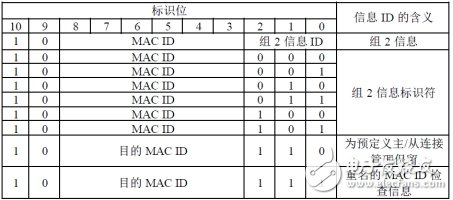
The MAC ID in group 2 may be the MAC ID of the sending node. The source MAC ID may also be the MAC ID of the receiving node. The destination MAC ID. When the connection is established through group 2, the endpoint will determine whether the source MAC ID or the destination MAC ID is in the group 2 transmission. The bus access priority is determined by the MAC ID value of the MAC ID portion of the identifier. When two or more group 2 transmissions are CAN bus arbitration, the information with a small MAC ID value will obtain bus access rights.
At present, the CANScope bus integrated analyzer of Zhiyuan Electronics has been equipped with CANPRO software free of charge, which can analyze the mainstream DeviceNet protocol.
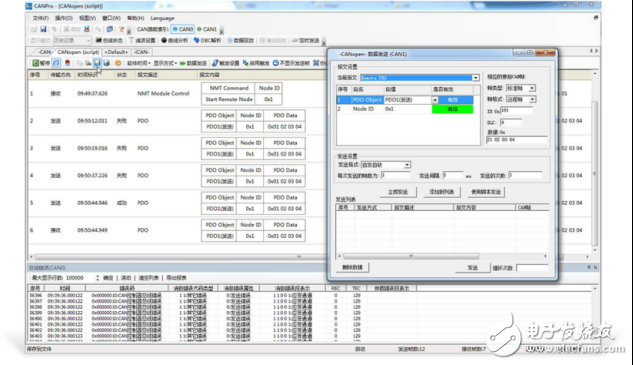
Figure 5 Protocol Analysis
KNL1-100 Residual Current Circuit Breaker
KNL1-100 Moulded Case Circuit Breaker is MCCB , How to select good Molded Case Circuit Breaker suppliers? Korlen electric is your first choice. All moulded Case Circuit Breakers pass the CE.CB.SEMKO.SIRIM etc. Certificates.
Moulded Case Circuit Breaker /MCCB can be used to distribute electric power and protect power equipment against overload and short-current, and can change the circuit and start motor infrequently. The application of Moulded Case Circuit Breaker /MCCB is industrial.
Korlen electric also provide Miniature Circuit Breaker /MCB. Residual Current Circuit Breaker /RCCB. RCBO. Led light and so on .
KNL1-100 Molded Case Circuit Breaker,KNL1-100 Small Size Molded Case Circuit Breaker,KNL1-100 Electrical Molded Case Circuit Breaker,KNL1-100 Automatic Molded Case Circuit Breaker
Wenzhou Korlen Electric Appliances Co., Ltd. , https://www.korlen-electric.com
