Bluetooth® LE (Low Energy) is rapidly gaining popularity in applications that combine convenience with smartphones and tablet terminals (such as watches, fitness/health equipment, etc.). In these applications, button-cell-powered devices are the most demanding, and in order to achieve longer battery life and higher performance, the demand for low power consumption is increasingly strong. Not only that, because users without wireless experience can connect to Bluetooth® LE through their smart phones, etc., the trend of Bluetooth® LE in many products is overwhelming. On the other hand, in order to use a wireless system such as Bluetooth® LE, it is necessary to perform the calibration confirmation at a specific experimental institution and obtain the radio certification prescribed by each country. Therefore, when researching the system from scratch, it requires sufficient knowledge of wireless and protocol. Otherwise, it is very likely that the product will stop stagnation before the product is about to be introduced to the market.
This article refers to the address: http://
In this case, ROHM (Rom)'s LAPIS Semiconductor has developed the industry's top low power consumption with support for Bluetooth® LE (9.8 mA when transmitting data, 8.9 mA when receiving data, and average current for 2 seconds of intermittent operation) 8μA) LSI (ML7105-00x). In addition, modules for obtaining time-consuming and labor-intensive Bluetooth SIG certification and domestic and international radio certifications are also being developed.
Here, the LSI and modules and the sample software and configuration files required to build the system are described.
First, the internal structure of the Bluetooth® LE LSI (ML7105-00x) will be explained. (figure 1)
![[Fig. 1] Internal structure of Bluetooth® LE LSI (ML7105-00x)](http://i.bosscdn.com/blog/e4/2f/7d/068da898724f018d83fb6da7ea.jpg)
The circuit block mounted on this LSI consists of a wireless unit (RF), a modem unit (MODEM), a Bluetooth® LE controller unit, a low-power logic unit, a power supply unit (Main Reg. / Low Power Reg.), and an oscillating circuit unit (26 MHz). /32kHz), host interface unit (UART, I2C, SPI, GPIO). The main functions of each unit are: the wireless unit provides 2.4 GHz data transmission circuit and data receiving circuit, and the transmission system converts the modulation signal input by the modem unit (modulator) into an analog signal through a D/A converter, and then passes through the local PLL and Signal superposition in the 2.4 GHz band. Then, it is amplified by the power amplifier to a sufficient power as an electric wave to be transmitted by the antenna. The receiving system inputs the received signals of various intensities captured by the antenna, and the small signals are amplified by the low noise amplifier. The latter mixer converts the frequency of the 2.4 GHz band to an intermediate frequency of a few MHz or so, and inputs it to the bandpass filter to select only the signals of the desired channel. The signal is then amplified by the limiter and transmitted to the modem unit (demodulator). These wireless units are characterized by the use of PLL direct modulation to optimize the overall circuit block for lower peak currents (below 10 mA).
Then, the controller unit performs encoding and decoding processing of the Bluetooth® LE data packet, and the device is discovered by the link processing unit (LL) and the protocol stack (GATT/ATT/SMP/GAP/L2CAP) and connected with the discovered device and provided. Two-way communication. In addition, through the linkage with the low-power logic unit, a circuit that suppresses leakage current when the power is turned off is newly developed. At the same time, the protocol processing firmware of Bluetooth® LE is optimized, and the data transmission and reception of data packets is shortened. Time, so that the power consumption at work is lower. The power supply unit then incorporates a main regulator and a low-power regulator to store data only through a lower-power, low-power regulator when not communicating. Through these designs, the overall leakage current is minimized. The oscillating circuit unit has a built-in 26MHz for main operation and 32kHz for low power operation. In particular, the main operation 26MHz oscillation circuit is stopped every time according to the connection interval of the Bluetooth® LE. Therefore, by adjusting, the time from the stop state to the start is minimized, thereby reducing the standby current. Finally, the host interface unit is equipped with Bluetooth® LE standardized HCI (UART) and LAPIS Semiconductor's exclusive BACI (SPI). HCI is primarily connected to a PC and can be used for wireless certification testing. BACI connects to a host microcontroller with Bluetooth® LE profiles and applications and provides Bluetooth® LE services.
BACI reduces access frequency by simplifying communication with the host. Moreover, a structure for starting the host by an event is adopted in the structural design, and therefore, it is a design that stops the host as much as possible to suppress power consumption. In summary, the LSI has designed a power consumption reduction structure on the entire structural module, thereby making it possible to continuously operate the button battery for more than three years. The host and stack structure is shown in Figure 2.
![[Figure 2] Host and Bluetooth® LE controller stack structure](http://i.bosscdn.com/blog/37/bd/1e/438257ede58740799771d28932.jpg)
[Figure 2 ] Host and Bluetooth ® LE controller stack structure
<Bluetooth® LE Module>
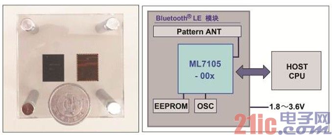
Next, explain the structure of the Bluetooth® LE module. (image 3)

[Fig. 3] Photograph and structure of the Bluetooth® LE module
This module also includes a Pattern ANT, RF matching circuit, EEPROM, and OSC in addition to the Bluetooth® LE LSI (ML7105-00x). LAPIS Semiconductor will adjust the RF performance through the Pattern ANT and RF matching circuits when shipped, so users can install them in the product without adjustment. The EEPROM can store configuration parameters that mainly contain RF adjustment values, communication modes, device addresses, and can store user's own parameters. The OSC consists of a 26MHz crystal oscillator and adjustment circuitry for the master clock and has been tuned to the frequency accuracy required by Bluetooth® LE.
This product is a SiP (System in Package) structure in which a large number of components are integrally packaged, so it can be handled in the same way as LSI. In addition, the product will be QDID certified by the Bluetooth SIG-certified component test (RF, PHY, LL, 4.0HCI, L2CAP, GAP, SMP, GATT/ATT) and will be provided as a module to the customer. Therefore, as a final product registration, only Embedding user-prepared profiles makes it easy to register with the Bluetooth SIG's product list. Also, in order to register, you need to register with the Bluetooth SIG members (founding members, affiliate members, and application members) in advance. In addition, the product is planned to be supplied after receiving domestic and foreign radio certifications. Therefore, Bluetooth® LE (output wave) can be operated directly in Japan and certified overseas regions, and customers can quickly import them into products in a short time. .
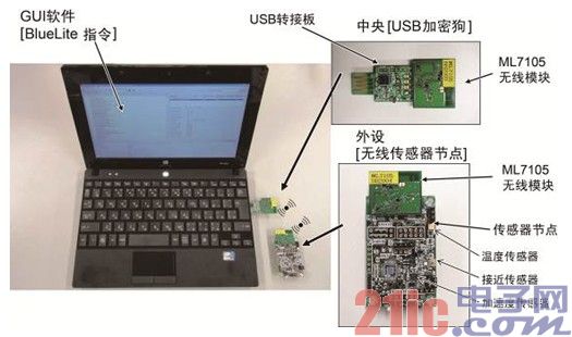
To improve the speed and speed of development of LAPIS Semiconductor's Bluetooth® LE products, the company has prepared evaluation kits and sample software. The evaluation kit (Figure 4) includes a USB dongle and wireless sensor node for Bluetooth® LE communication (various sensor data reception, LED ON/OFF control) via PC.

[Figure 4] Bluetooth® LE Development Evaluation Kit
The sample software (Figure 5) contains a unique configuration file VSSPP (Vendor Specific Serial Port Profile)/VSP (Vendor Specification Profile) that can be installed on the host microcontroller. With this software, P2P can be easily confirmed by UART-based terminal communication ( Peer-to-peer computing, PEER-TO-PEER) Bluetooth® LE communication control.
In addition, LAPIS Semiconductor has opened a technical support website.
(URL: https://)
The website provides relevant data sheets, user manuals, design guides, evaluation kit user manuals, etc. to support the development of users.
![[Figure 5] Structure of the sample software](http://i.bosscdn.com/blog/c1/ee/0f/9050fb6682fe8011904b698fce.jpg)
[Figure 5] Structure of the sample software
Pairing is implemented at the time of connection, and the connected devices are restricted to implement encrypted data communication. In addition, it can be used as a point-to-point Bluetooth® LE device to communicate with a smartphone, using a dedicated smartphone app to confirm the service of a unique profile.
<Bluetooth® LE Profile>
In order to communicate correctly using Bluetooth® LE, the same configuration file is required as the master terminal and the slave terminal. The configuration file is a hierarchical structure with internal eigenvalues ​​that define several services and their attributes (read/write, etc.). For example, there are Heart Rate Service and Device Information Service in the Heart Rate Profile. LAPIS Semiconductor has developed standard configuration files. All the configuration files are jointly developed with third parties and are expected to be available for delivery. It is expected to support the migration to the user platform.
<future outlook>
In the future, the application range of Bluetooth® LE is expected to expand further, and the demand for lower power consumption, smaller size, and easier system development is growing. Therefore, following the current ML7105 series, LAPIS Semiconductor is developing a follow-up series. According to the plan, the subsequent series not only reduces power consumption, but also meets the needs of miniaturization. The WL-CSP (Wafer Level Chip Size Package) in ultra-small and thin package will enrich the product lineup. In addition, in order to introduce Bluetooth® LE more easily than ever before, LAPIS Semiconductor plans to develop SiP modules with built-in host microcontrollers and various sensors developed by ROHM Group based on the modules currently under development.
LAPIS Semiconductor is also exploring the need for further high performance (high speed transmission, tree connection, etc.). In combination with the latest Bluetooth® LE Core Spec 4.1 standard, the company will continue to provide customers with one-stop solutions in the future.
Face Mask play a very important protective
role in the outbreak, mainly to protect the respiratory tract, can prevent the
spread of respiratory droplets, reduce the invasion of viruses or bacteria,
prevent the role of infection, but also can prevent the invasion of harmful
substances, also can reduce the probability of cross-infection.
In the outbreak to correctly choose masks and use Medical Masks,
Disposable mask, to choose the application of surgical masks or n95 masks, such
as disposable cotton masks, disposable paper masks, and anti-smog masks are not
recommended to wear, because their tightness is not good, cannot prevent
viruses and bacteria, play a preventive role.
At the same time, wearing a mask cannot be used continuously
for a long time, it is generally recommended to change every four hours,
wearing for a long time may absorb more viruses or bacteria on the surface of
the mask and reduce the defense ability.
Face Mask
N95 mask,Medical masks,Disposable mask,Protective mask
YFJ TECHNOLOGY (HK) CO.,LIMITED , http://www.yfjpower.com
