Abstract In the practical application of electric vehicle power battery, it takes a long time to test the actual road condition. The experiment period is long, the process is complicated, and the cost is high. In order to solve this problem, based on the measured data of the battery management system (BMS) and C# data acquisition and monitoring system based on Freescale's MC9S12XEG128 microcontroller, the Arbin-based electric vehicle test system (EVTS) designed the power battery simulation experiment platform. The real-time sampling, display, storage and actual road condition simulation test of the battery multi-parameters are realized, thereby realizing the same battery work data obtained in the laboratory for real vehicle external test. The test results show that the program can obtain the same results as the actual road test.
This article refers to the address: http://
With the intensification of environmental pollution, electric vehicles have received more and more attention for their energy conservation and environmental protection. In the research and development of electric vehicles, the research and manufacture of vehicle power batteries and their management systems occupy an important position. With the maturity of electric vehicle technology, electric vehicles have gradually transformed from experimental products to products. In the electric vehicle test, the actual road condition test of the battery has an important position, but in the application, the actual road condition test period is longer and the cost is higher, and the bench simulation and actual operation are different. This test procedure can be simplified by the design of this experimental scheme. The solution relies on the battery management system (BMS) and the battery-based monitoring system based data monitoring and acquisition system to collect plug-in Ni-MH fast-charge hybrid bus external test battery data, using the American Arbin Electric Vehicle Test System (EVTS) The MITS host computer control software performs simulation simulation, and the same battery test data as the external road experiment can be obtained in the laboratory. At the same time, the discharge of the battery is fed back to the grid through the test system, and the electric energy can be recycled. The scheme has good reproducibility. To a large extent, the cost of the experiment is saved.
1 plug-in NiMH fast-charge hybrid bus
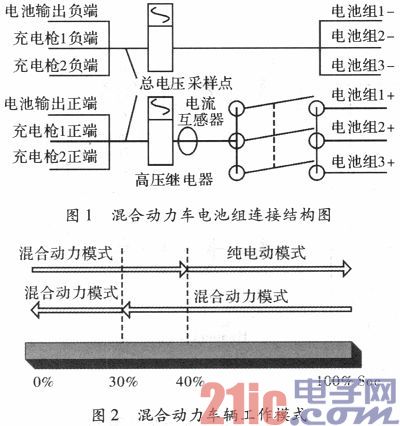
The plug-in Ni-MH fast-charge hybrid bus uses three sets of 300 V/40 Ah battery packs in parallel to form a 300 V/120 Ah battery pack, as shown in Figure 1. Nickel-hydrogen (Ni-MH) batteries are alkaline batteries. Because they do not have heavy metal pollution problems, they are called “green batteriesâ€. At present, the performance indicators of nickel-metal hydride batteries are: energy density (3 h) is 55-70. Wh/kg, power density is 160-500 W/kg, fast charging from 40% of full capacity to 80% is 15 min, cycle life exceeds 1 000 times (DOD=100%), nickel-hydrogen battery has energy density The power density is high, the fast charging box has good deep discharge performance, high charging and discharging efficiency, no heavy metal pollution, and the advantages of full sealing and maintenance-free. The bus works in pure electric and hybrid mode. When the remaining battery capacity (Soc) is <40%, it works in hybrid mode, >40%, when working in pure electric mode, the working mode is switched as shown in Figure 2; in pure electric mode. The maximum speed is 70 km / h, the car is used as a bus, generally working in pure electric mode, the battery Soc is 80% ~ 30%, that is, each discharge is 50%, the discharge is 60 Ah, can guarantee pure Driving in electric mode is about 30 km; charging with 3C high current, Soc is charged from 30% to 80%, that is, the charging amount is 60 Ah, it takes about 10 minutes to achieve charging performance for 10 min and running for 30 km.
2 Battery Management System (BMS)
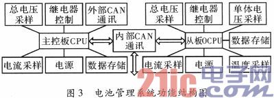
The battery management system adopts a distributed master-slave structure. Each set of slave system is responsible for 21 module voltages, total voltage, 12 channels of temperature, sampling of branch current, and battery remaining capacity (Soc) calculation for each group of 300 V/40 Ah batteries. CAN communication with the main control board. The main control board is responsible for the total current, the sampling of the total voltage, the calculation of the remaining battery power, the fault judgment, the system protection and the CAN communication of the master-slave internal CAN communication and the master control and the vehicle controller (ECU). The structure is shown in Figure 3. . The sampling interval of the current in the system is 10 ms, which can meet the calculation requirements of the battery safety time method. The calculation of the battery Soc is determined by the integration method and correction.
The battery remaining capacity (Soc) ampere-hour method is calculated as follows

In the formula, α(t) is the charge and discharge efficiency, which is related to the battery temperature and Soc, i(t) is the charge and discharge current value of the battery, and Q is the rated capacity of the battery, and the unit is Ah.
The calculation formula of the electric quantity digital integral is as follows
Q(nT) is the battery power at nT, Q(0) is the initial battery charge, and the unit Ah, i(nT) is the current value at nT, the unit is ampere, and T is the current sampling period.
CAN communication: CAN bus is a serial data communication protocol developed by German BOSCH from the early 1980s to solve the data exchange between many control and test instruments in modern automobiles. It is a multi-master bus. The communication medium can be twisted pair, coaxial cable or optical fiber with a communication rate of up to 1 Mbit·s-1. The data length is up to 8 Bytes, which will not occupy too long bus time, thus ensuring the real-time communication; CAN protocol adopts CRC test and can provide corresponding error handling function to ensure the reliability of data communication. The MC9S12XEC128 MCU has two CAN controllers. One CAN controller of the main board is used for internal CAN communication of the master and slave boards, and the other is used for communication between the main board and the vehicle controller (ECU). The CAN communication rate in the system is set to 250 kbit·s-1 and the communication cycle is 100 ms.
The external CAN uses the Zhou Ligong CTM8251T universal CAN isolated transceiver. The CTM8251 integrates all necessary CAN isolation and CAN transceiver devices. The main function of the chip is to convert the logic level of the CAN controller into the differential level of the CAN bus and have the isolation function of DC2500V, which conforms to the ISO11898 standard. The principle is shown in Figure 4.

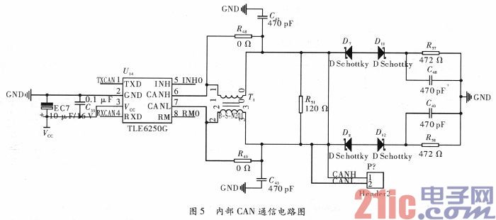
Internal CAN communication uses TLE6250G as CAN transceiver, TLE6250 is packaged in P-DSO-8-3, small size, data transmission speed up to 1 Mbit·s-1, used in 12 V or 24 V automotive and industrial systems. The principle is shown in Figure 5.
3 data monitoring and acquisition system
The data monitoring and acquisition system adopts Visual C#2010 software platform, and receives the real-time CAN sampling data of BMS through Zhou Ligong USB-CAN II smart card and CAN-bus interface library function, and performs data decoding and real-time monitoring display in the host computer software. The Access database stores data, and the data can be directly transferred out and saved to Excel format. The database and stored Excel file includes 63 module voltage values ​​of 3 groups of batteries, 36 temperature values, total voltage, total current and 3 branch currents, Soc value and storage time in the master and slave boards, which can be completely recorded. The operating state of the vehicle for later battery state studies.
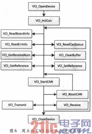
Zhou Ligong CAN-bus interface library function usage: Put the library function files in the working directory. The library function file has a total of three files: ControlCAN.h, ControlCAN.lib, ControlCAN.dll, and folder kerne ldlls. The program imports the dll dynamic library through the DllImport function, and declares the data structures and functions contained in the library. The interface function uses the flow.
4 Arbin's electric vehicle test system
The Arbin Electric Vehicle Test System (EVTS) in the United States can simulate the working state of the battery in the original vehicle's external road conditions through the actual battery data of the vehicle's external road conditions saved by the battery management system's data monitoring and acquisition system. . Arbin's Electric Vehicle Test System (EVTS) is a series of high-power automated battery test systems designed for research and testing of electric or hybrid electric vehicle batteries. The system provides programmable power supply and electronic load for automatic charge and discharge test and simulation test. The device has extended functions such as auxiliary voltage test, auxiliary temperature test and CAN BUS communication. The EVTS used in this solution can simultaneously obtain dual 400 V/200 A output, and two parallel connections can get 400 V/400 A output. When the car is purely electric, the maximum discharge current of the battery is limited to 360 A, so the system can fully simulate the state of charge and discharge of the battery during the actual operation of the car. The battery test is mainly realized by the programmable simulation function in the upper computer control software MITS of Arbin's electric vehicle test system (EVTS), but the simulation data is stored in the data monitoring and acquisition system depending on the bus external test. Battery data.
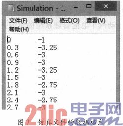
The programmable simulation of the MITS software uses the input data from the non-configured dynamic mechanism as a control function to control the output of the test system to the battery.
(1) Enable simulation control. The emulation control option can be turned on via the emulation control in the system configuration arbinSys.cfg, Advanced Options directory. If this option is not checked, the four emulation features in the control mode are not available. Through simulation control, the user can easily use the data in the simulation file as a parameter for complex control to obtain an arbitrary, transient function. The emulation file must be saved as a text file and stored in the C:\Arbinsoftware\Mits_Pro\Data directory. The time and current are stored as separate columns. There is no column name, only data, and tabs between the two columns. Separated, the units of time and current are seconds and amps, respectively, and the positive and negative of the current indicates charging and discharging.
(2) Edit the simulation option table.
1) In the test options table, select the control method and specify the simulation file. The control method can be current, voltage or power simulation.
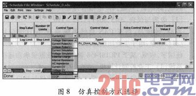
2) Specify the simulation file, right-click the area below the control value, select the specified simulation file, and select the file to be simulated in the pop-up dialog box.

3) Set some qualifications in the program, including maximum charge and discharge voltage, current, sampling time and program running time.
5 working conditions simulation results
When the simulation data is actually tested by the original vehicle, the current data of the BMS is sampled, the current control interval is set to 0.3 s, the whole process time is 50 min, and the sampling period of Arbin's MITS host computer control software is set to 100 ms. The process is pure electric mode. When the battery's Soc is higher than 70%, the battery does not perform brake feedback. When the battery power is lower than 70%, there is a brake feedback process. The whole process includes starting acceleration, continuous climbing, continuous down. Slope and continuous acceleration and brake feedback. The voltage curve of Arbin sampling in the actual external circuit and simulation is shown in Figure 10, and the current curve is shown in Figure 11.
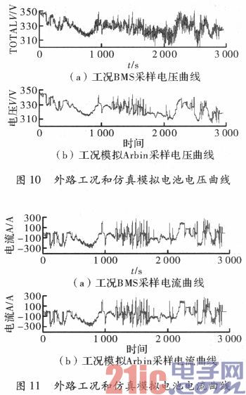
As can be seen from the comparison chart, the same battery operating state as the external test can be obtained by using the Arbin Electric Vehicle Test System (EVTS).
Comparison of original external test and simulation simulation experimental data. The original external test data: initial Soc=85, the end of the test Soc=37, the total Soc is reduced by 48%, and the discharge is 57.6 Ah. In the simulation, the total discharge of the Arbin electric vehicle test system is 72.587 Ah, the total charge is 14.87 Ah, the power consumption is 57.717 Ah, and the variation of the battery Soc is 48%. BMS data during simulation: initial Soc=83, simulation end Soc=33, Soc reduced by 50%, and discharge amount was 60 Ah.
The BMS measured the discharge amount during the simulation test is greater than the Arbin electric vehicle test system. The reason analysis: It can be seen from the connection of the high-voltage control box in Figure 1, the charging gun is connected in parallel with the battery output, and when the system starts working, part of the vehicle is used. The electrical output of the appliance is output by the battery. The output current is about 2.5 A, and the test time is 50 min. That is, the power consumption of the vehicle is 2.08 Ah, and the total power consumption is 59.797 Ah. Considering BMS Regarding the problem of battery charging efficiency, the measurement data is valid. This test can not only simulate the external road running situation, but also calculate the braking feedback energy of the vehicle in the process through the electric vehicle test system. In the experiment, when the Soc change is 48%, the vehicle braking feedback energy is 14.87 Ah. The feedback Soc is 12.39%.
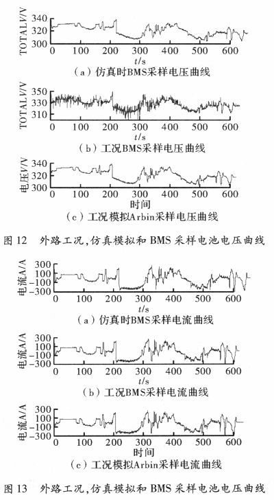
The actual external circuit of the second half of the laboratory simulation, the voltage waveform of the BMS sampling during Arbin sampling and simulation experiments is shown in Figure 12, and the current waveform is shown in Figure 13. Comparing the voltage and current curves, it can be seen that the laboratory simulation can track the external experimental data well, but in order to ensure the real-time sampling, the real-time performance of the sampling data is affected to some extent, and the experimental data synchronization is later. There is still a need for improvement.
6 Conclusion
Combined with the existing experimental conditions, the battery state of the external experiment can be well simulated in the laboratory by Arbin's MITS upper computer control software and the actual external test data of the electric vehicle battery management system. The experiment proves that the simulation experiment can basically replace the external experiment of the battery, obtain more accurate battery data than the original bench test, and simplify the experiment process. At the same time, the battery discharge in the experiment can be directly fed back to the grid through the Arbin electric vehicle test system. , so that the electrical energy is recycled, saving experiment time and cost.
Sunpower Solar Panels,Glass Flexible Solar Panel,Flexible Photovoltaic Cells,High Efficiency Solar Panel
Shengtian New Energy (Shenzhen)Â Co., Ltd. , https://www.stenergysolar.com
