LED TV means LCD TV with LED backlight technology. At present, LCD TVs with LED backlights have a series of advantages such as thinness, energy saving and environmental protection, and have become mainstream products in the TV and display markets. By adjusting the LED backlight supply voltage or operating current, it is easy to change the LED's luminous intensity, which makes the LCD TV LED backlight dynamic adjustment technology for the purpose of reducing power consumption quickly applied, and the LED nanosecond level The response speed guarantees the dynamic adjustment of the LED backlight.
The LED backlight module distinguishes between the bottom backlight and the side backlight. The bottom backlight is also called the direct type, which means that the LED light is installed on the back of the liquid crystal and evenly distributed behind the panel. The bottom backlight method has good heat dissipation, uniform overall brightness, realistic picture detail, and good dynamic backlight effect. Currently, it is mainly used in the large-size and high-end LCD TV market. The side backlight is also called the side-in backlight, which means that the LED light is installed on the upper and lower sides or around the liquid crystal panel, and the light is transmitted by the light guide plate to realize the screen backlight. The backlight has a simple structure, is easy to realize thin design, and has low cost. Currently, it is mainly used for low-end LCD TV products.
This paper designs a liquid crystal TV dynamic backlight system based on FPGA (Field Programmable Gate Array), which adopts LED side backlight mode, which is in line with the current mainstream LCD TV backlight application.
2 TV dynamic backlight
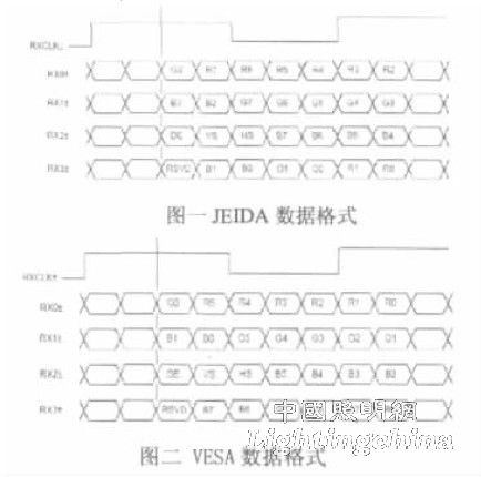
In the past, the TV motherboard transmitted the image signal to the LCD panel through LVDS (Low Voltage Differential Signal Transmission), and the backlight was controlled by the LED driver. The display system and the backlight system were relatively independent. When the image signal is transmitted through LVDS, there are two formats, one is JEIDA standard, as shown in Figure 1; the other is VESA standard, as shown in Figure 2. The LVDS signals of the LCD panel generally have four to five pairs, one pair is a clock signal, three to four pairs are data signals, and the data signal and clock signal speed is 7:1.

LCD TV dynamic backlight adjustment distinguishes LED backlight component from full-screen brightness PWM (pulse width modulation) control, LED backlight assembly lateral sub-area brightness PWM control, LED backlight assembly vertical sub-area brightness PWM control, RGB sub-area brightness control and synthesis control. In order to enable the LCD TV to achieve sub-area backlight brightness PWM control, the dynamic image signal must be analyzed accordingly. The image brightness information of each area is calculated by the inserted FPGA board, and then the LED control is driven according to the average brightness signal of the area statistics. The chip separately adjusts the backlight brightness of the corresponding backlight area. The FPGA board simultaneously transmits image signals to the LCD panel to achieve synchronization of the backlight and the image, that is, the dynamic backlight adjustment function of the LCD TV is realized. The LED control chip must have multiple outputs and each output can be independently adjusted, so that the chip can adjust the brightness of the corresponding area according to the brightness information of the image of each area of ​​the screen, and turn down the backlight when the screen displays dark scenes. The brightness, which in turn reduces energy consumption. An example of the backlight adjustment effect is shown in Figure 3.
3 system design
The 32-inch LCD TV designed in this paper uses LED side backlighting. Two light bars are installed on the upper and lower sides of the TV panel. Each light bar has 4 strings of LEDs. Each string of LEDs has 10 LED lights and 160 LED lights. The four strips have a total of 16 strings, corresponding to 16 dimming areas.
The FPGA device uses the XC6SLX16 device from the Xilinx, Inc. Spartan6 family. Spartan-6 FPGAs are the new Xilinx FPGA applications with the lowest cost, best-in-class FPGAs with a 45nm low-power copper process that delivers the best balance of cost, performance and power. Built-in system-level modules including DSP slices, high-speed transceivers, and PCI Express interface cores provide a higher degree of system-level integration; advanced power management technology and an optional 1.0v low-power core enable Spartan-6 FPGA power consumption Lower; supports over 12Gbps of memory access bandwidth; High-performance integrated memory controller supports DDR, DDR2, DDR3, and mobile DDR memory, hard-core multi-port bus architecture provides predictable timing and up to DDR2/DDR3 800 (400MHz) Performance.
The LED driver chip uses the AS3693B control chip from Austriamicrosystems. The chip has a conceptual design that controls the external FET and features a patented power-saving technology that actively regulates the LED power supply to minimize system power consumption. The chip features an I2C (Inter-Integrated Circuit) and SPI (Serial Peripheral Interface) interface and 16 independent PWM-regulated channels, each with a current accuracy of 0.5%, enabling the LCD backlight to achieve the most accurate color and brightness control; The external clock and sync input allow the LCD backlight and TV image to be synchronized, enabling “block dimming control†for the highest possible contrast.
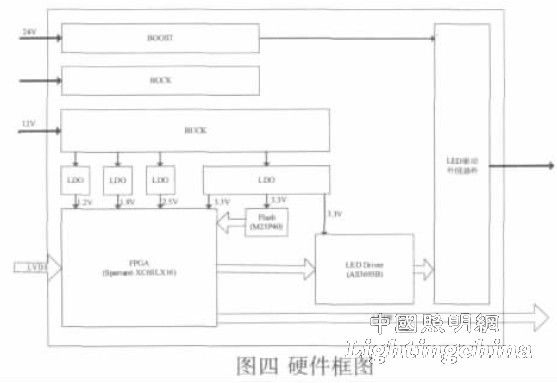
The FPGA board requires a 1.2V, 1.8V, 3.3V supply voltage. The AS3693B requires 3.3V. The BUCK (buck converter) must be used to convert the 12V to the required voltage. The hardware design of the LED backlight system is shown in Figure 4:

