When a current-carrying metal or semiconductor wafer is placed vertically in a magnetic field, a potential difference is generated at both ends of the sheet. This phenomenon is called the Hall effect. The difference in potential at both ends is called the Hall potential UH, and its expression is
UH=K·Ia·B/d
Where K is the Hall coefficient, Ia is the current passing through the sheet, B is the magnetic induction of the applied magnetic field (Lorentz force Lorrentz), and d is the thickness of the sheet. It can be seen that the sensitivity of the Hall effect is proportional to the magnetic induction of the applied magnetic field. Among them, the Hall effect of the metal plate in the magnetic field, the Hall coefficient of the pure metal is relatively small, and the Hall coefficient of the semiconductor material is several orders of magnitude, so semiconductor materials such as silicon, germanium, indium arsenide and indium antimonide are generally used. As a Hall element.

Figure 1 S-5711ANDL-I4T1G pin arrangement diagram
Among them, contactless sensing will be the trend of the times. In the contactless sensor, Hall Effect Sensor has won wide application space in the automotive field due to its high reliability. The advantage of the Hall current sensor is that the circuit form is simple and the cost is relatively low. The disadvantages are accuracy, poor linearity, slow response time, and large temperature drift. In this paper, the correction method for reducing the nonlinearity is discussed mainly for the nonlinear problem of Hall current sensor.
Correction method analysisThe correction method is described by taking the integrated S-5711ANDL-I4T1G Hall sensor as an example.
1 Introduction to S-5711A
The S-5711A series is a high sensitivity, low current consumption Hall IC (Magnetic Switch IC) developed using CMOS technology. The intensity of the magnetic flux density can be detected to change the output voltage. By combining with the magnet, on/off detection of various devices can be performed.
The pin arrangement of the 1S-5711ANDL-I4T1G is shown in Figure 1.
2S-5711A working characteristics
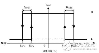
The operating characteristic curve of the S-5711A series Hall integrated sensor is shown in Figure 2. If the magnet is close to the sensor IC, VOUT changes from "H" to "L" when the magnetic flux density in the vertical direction exceeds BOPN or BOPS for the marking surface of this IC; if the magnet is away from this IC, the magnetic flux density is lower than BRPN Or BRPS, VOUT changes from "L" to "H".
It is known from the general operating characteristics of the Hall switch integrated sensor that the hysteresis BH is very advantageous for the reliability of the switching operation. The operating characteristic curve of the Hall switch integrated sensor reflects the relationship between the applied magnetic field and the sensor output level. When the applied magnetic induction is greater than the "on" magnetic induction, the output level changes from high to low and the sensor is on. When the applied magnetic induction is less than the magnetic induction of the "off" of the release point, the output level changes from low to high and the sensor is off.
The advantages of this type of sensor are: it is not affected by the polarity of the magnet, which can reduce human error during production and assembly; from mechanical to IC switch, its low current consumption is also an advantage. The application environment is also very wide, mainly including mobile phones (sliding cover / opening and closing cover / flip cover) and other occasions that require the opening and closing cover or opening and closing components to realize the whole system or module switching function.
2 Correction method

Figure 2 S-5711A operating characteristics
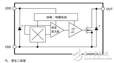
The S-5711ANDL-I4T1G integrated sensor features high sensitivity and a wide operating temperature range (-40 to +85 °C). Generally, the Hall voltage VOUT is nonlinearly related to the magnetic induction B, and its absolute linearity is 29%. And there is an unbalanced voltage UHe, which, if used improperly, must affect the accuracy of the detection system. The internal circuit principle of the S-5711ANDL-I4T1G chip is shown in Figure 3.

Figure 3 S-5711ANDL-I4T1G chip internal circuit principle
Its output voltage is determined by the following formula:
UH=KHIHBcosθ+KeIH
KH in the formula - Hall sensitivity
IH - Hall sensor drive current;
B——magnetic induction strength;
Cosθ——the angle between the normal of the component plane and B;
Ke———The imbalance factor.
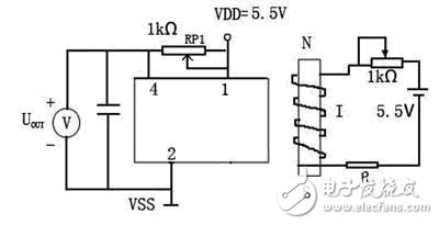
KeIH=UHe is called unbalanced voltage, (UHe/UH)) & TImes; 100% is called unbalance rate, and it is set to Re. The Re of the Hall element is generally about ±10%. Both KH and B produced by the current being tested are non-linear factors. A circuit for eliminating unbalanced voltage and improved nonlinearity is shown in FIG.

Figure 4 Circuit for eliminating unbalanced voltage and improved nonlinearity
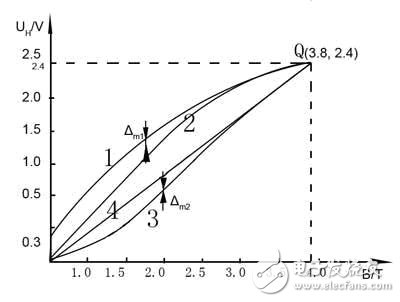
The current I in Figure 4 corresponds to the current being detected, and the chip 3 is not used. Changing the current I changes the magnetic induction B. The test curve is shown in Figure 5.

In Fig. 5: curve 1: R14 = 0; curve 2: R14 → ∞; curve 3: R14 = 100 Ω. Line 4 is called the theoretical linearity fit curve and is the line connecting the origin (0,0) and the limit point Q (3.8, 2.4). Curve 1 is not added with the correction potentiometer RP1, at which time the unbalanced voltage UHe = 0.3V, the imbalance ratio Re = (UHe / UH) & TImes; 100% = (0.3 / 2.4) & TImes; 100% = 12.5%.
The linearity is analyzed as follows.
Linearity is the proximity of the static characteristics of the measurement system to the selected fitted line y=b+kx.
δL=(|Δm|/Ym)&TImes;100%
Where Δm is the maximum fit deviation of the static characteristic from the selected fitted straight line;
Ym - the limit value of y.
The method of determining the fitted straight line is different, and δL is also different. In this paper, the absolute linearity method is used. The value obtained by this method is generally larger than that of the least squares method.
For the curve 1 in FIG. 5: |Δm1|=0.7V, the limit value Ym=UHm=2.4V, the linearity δL1=29% is known by the formula δL=(|Δm|/Ym)×100%, that is, the Hall sensor When the correction circuit is not applied, the absolute linearity is 29%, which is relatively large. After the circuit is calibrated, the optimal working state is curve 3 in Fig. 5, with |Δm3|=0.13V, and the same reason δL3=7.6%, the linearity is greatly improved. Curve 2 (R14→∞) in Fig. 5: The unbalanced voltage is eliminated and good linearity is obtained. However, at the same time, under the same magnetic induction intensity, that is, the same intensity detected current, the output voltage drops, that is, the sensitivity of the sensor decreases, but this deficiency can be compensated by the post amplifier.
ConclusionThrough nonlinear correction, the Hall current sensor of this design has high precision and good linearity, and has strong practicability. Through experimental and theoretical analysis, the circuit designed in this paper can find the optimal linear working state of the Hall sensor and eliminate the unbalanced voltage.
Table Air Purifier,Table Top Air Purifiers,Table Top Air Filter,Tabletop Hepa Filter
CIXI KYFEN ELECTRONICS CO.,LTD, , https://www.kyfengroup.com
