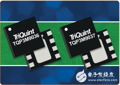
With the rapid growth of TD-LTE and the development of base stations towards multi-frequency multi-mode technology, newly developed devices need to have a shutdown function that allows the system to easily turn off other functions while transmitting or receiving. In addition, for devices in the wireless infrastructure market, customers need a more integrated solution while maintaining high linearity performance and meeting lower power requirements. At the same time, in order to respond to the trend of miniaturization of base stations, high integration and efficient RF solutions are the goal of continuous efforts.
The low noise amplifier (LNA) is located in the receiving link where the distance signal is captured very close. All subsequent processing is based on the low noise amplifier amplified signal, so a low noise amplifier is the key device that determines the overall performance of the system. . As wireless environments become more congested, operators must achieve optimal reception under all conditions to maintain their claimed data rate performance, so the importance of low noise amplifiers cannot be ignored.
Although most smartphone users don't know the difference between WCDMA and LTE, they can't fully understand the difference between different data rates, but consumers pay attention to the performance of phone drop, signal attenuation, upload/download speed. For operators, speed is good, slow is bad, and dropped calls mean lost customers. Every loop in the value chain, including manufacturers, RF solution providers and operators, has more than ever reason to achieve a data performance.
For example, TriQuint's two ultra-low noise amplifiers, the TQP3M9036 and TQP3M9037, offer noise figure performance of less than 0.5 dB, as well as high linearity performance and high gain. To provide greater flexibility in TD-LTE multimode base stations, the new low noise amplifiers also feature a shutdown mode.

Designing a low noise amplifier to meet market challenges is a daunting task. At the lowest possible current, try to balance the conflicting requirements of high gain, low noise, high linearity, 50 ohm matching input and output ports, and unconditional stability. Each electronic design inevitably involves balancing performance goals that are interdependent. In this product case, noise matching is relative to gain and input return loss, stability versus gain, noise figure, linearity, and of course cost-effective versus performance, all of which are major considerations.
The best choice for TriQuint to meet these needs is the pHEMT process in gallium arsenide (GaAs) enhanced mode with a transition frequency of 45-GHz, a maximum current of 325 mA/mm, and a high transconductance of 600 ms/mm. Enhanced mode is becoming more and more popular in the manufacture of ultra-low noise devices because it eliminates the need for a negative supply voltage. The cascading topology is chosen due to its inherent high gain, the ability to achieve wide bandwidth and high stability, and the relatively low number of components for two transistor circuits. Low noise amplifiers typically operate between 15% and 20% of their maximum drain current for optimum noise figure, linearity, and reliability. TriQuint simplifies RF connectivity and design for base station manufacturers through high performance and cost effective integration.
Although not too long ago, a noise figure of less than 1 dB and an output third-order intercept (OIP3) of 33 dBm were generally acceptable, but performance requirements are now higher. The low noise figure of the first-stage low-noise amplifier of the base station directly affects the sensitivity of the receiver, and the third-order linearity affects the dynamic range of the system related to channel interference. Ultra-low noise performance through integrated, packaged low noise amplifiers has never been possible in the past, but it is different now. TriQuint's two new integrated, surface mount gallium arsenide (GaAs) E-pHEMT low noise amplifiers from 400 to 1500 MHz and from 1500 to 2700 MHz with noise figure 0.45 dB or lower and OIP3 of +35 dBm , at least 19 dB gain requirement. These coefficients are the best performance of an integrated low noise amplifier covering these frequency ranges in the commercial market today. By integrating key functions into industry-standard packages, TriQuint's devices simplify the RF design process while achieving superior low noise performance.
Introduction of the new low noise amplifierThe new low noise amplifier is fabricated in TriQuint's 0.35 micron pHEMT enhancement mode process, covering 400 to 2700 MHz, for most licensed and globally non-standard wireless bands used worldwide. Accordingly, these new devices are also well suited for infrastructure applications, including cellular base stations, tower-mounted amplifiers (TMAs), small cellular wireless networks, repeaters, LTE networks operating in the 700 MHz band, and using UHF spectrum. Emerging wireless systems with blank signal spectrum.
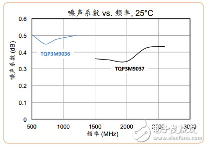
The TQP3M9036 low noise amplifier covers 400 MHz to 1500 MHz with a noise figure of 0.45 dB, a gain of 19 dB at 900 MHz, and high linearity (+35 dBm OIP3). The TQP3M9037 operates from 1.5 to 2.7 GHz with a noise figure of 0.4 dB, a gain of 20 dB at 1900 MHz and an OIP3 of +36 dBm. The superior noise performance of these two products can be displayed in graphics. The noise figure of TQP3M9037 and TQP3M9036 is shown in Figure 2. From 1700 to approximately 2300 MHz, the noise figure of the TQP3M9037 is actually less than 0.4 dB, which can be as low as 0.33 dB around 1900 MHz. The noise figure of the TQP3M9036 (between 700 and 900 MHz) is typically below its 0.45 dB rating, never above 0.47 dB over the entire band and down to 0.41 dB at 800 MHz.

Rectifier bridge is to seal the rectifier tube in a shell. Points full bridge and half bridge. The full bridge connects the four diodes of the connected bridge rectifier circuit together. The half bridge is half of four diode bridge rectifiers, and two half bridges can be used to form a bridge rectifier circuit. One half bridge can also be used to form a full-wave rectifier circuit with a center-tapped transformer. Select a rectifier bridge to consider. Rectifier circuit and operating voltage.
Bridge Rectifier,Original Bridge Rectifier,Full Bridge Rectifier ,Diodes Bridge Rectifier,Single Phase Rectifier Bridge, Three Phase Bridge Rectifier
YANGZHOU POSITIONING TECH CO., LTD. , https://www.pst-thyristor.com
