Floating in _IN_FLOATING
With pull-up input _IPU
With pull-down input _IPD
Analog input _AIN
Open drain output _OUT_OD
Push-pull output _OUT_PP
Open drain multiplexed output _AF_OD
Push-pull multiplexing output _AF_PP
4 input + 2 output + 2 multiplexed output, a total of 8 modes, the following is the working mode of the eight modes:
GPIO floating input _IN_FLOATING mode works as follows:
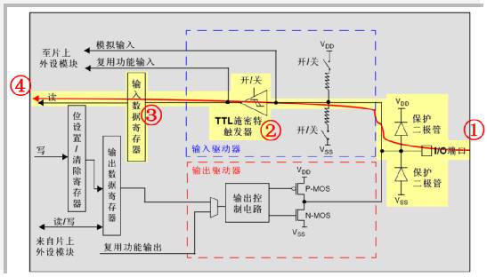
The above screenshot is the schematic diagram of the floating input mode. The shaded part of the figure is inactive in the floating input mode, especially the lower half of the output circuit . In fact, the output circuit and the input port are in this case. Isolated state.
The yellow highlight shows the data transfer channel. The external level signal is sent to the STM32 via the left-numbered I/O port. The numbered 2 Schmitt trigger is shaped and sent to the “input data register†number 3. At the other end of the "input data register" (number 4), the CPU can read the status of the level change of the I/O port at any time via the internal data bus.
GPIO with pull-up input _IPU mode works:
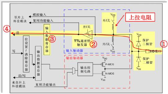
The figure above is a schematic diagram of the STM32 GPIO with pull-up input mode.
Compared with the floating input mode described above, only a pull-up resistor is connected to the data channel. According to the STM32 data sheet, the pull-up resistor has a resistance of 30K~50K ohms. Similarly, the CPU can read the state of the I/O port's level change through the internal data bus at the other end of the "input data register" at any time.
GPIO with pull-down input _IPD mode works:
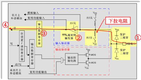
For the input pull-down mode input, a pull-down resistor is connected to the lower part of the data channel.
According to the STM32 data sheet, this pull-down resistor is also between 30K and 50K ohms.
For adding pull or pull down resistors:
1. When using the microcontroller as an input, assume that we connect a button directly to the ground (or power) on the IO port.
Because the button is pressed, it is suspended without pressing the pin. It is difficult for the microcontroller to detect if the button is pressed.
So artificially pull up (or pull down). To determine the state of the IO input level when not pressed
2. Can improve the anti-interference energy of the chip
3. When the IO port of the MCU is output, if the pull-up resistor is not connected, only the sink current can be supplied. Unable to output current to drive an external device. Pull-up resistors also need to be considered at this time. This can make the IO output high level.
GPIO analog input _AIN mode works: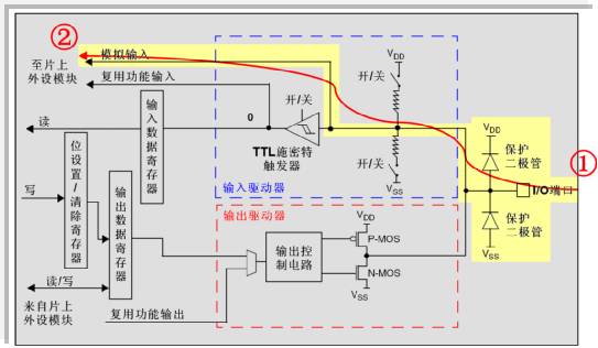
If the STM32 is configured for analog input mode, the working principle is simpler. The signal is numbered from the port numbered 1 on the left and the end numbered 2 from the right directly enters the AD module of the STM32 microcontroller.
Careful friends can see the data channel pull-down resistors and Schmitt trigger, this time is in a state of OFF, "the input data register" can not reflect the state of the level variation on the IO port, and for In other words, in the analog input state, the CPU cannot read the data of the IO port change through the "input data register".
The above analysis is the working principle of the input mode of the IO pin of the GPIO module. The following describes the working principle of the GPIO output mode.
GPIO open-drain output _OUT_OD mode works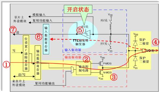
The figure above shows the working principle of the GPIO open-drain output mode.
When the CPU writes data at the number 1 terminal by "bit setting/clear register" or "output data register"
This data bit will be transferred to the I/O port numbered 4 via the number 2 output control circuit.
If the CPU writes a logic "1", the number 3 N-MOS tube will be off.
The level of the I/O port will be determined by the external pull-up resistor.
If the CPU writes a logic "0", the number 3 N-MOS tube will be on.
At this time, the level of the I/O port is pulled to the zero potential of "ground" by the numbered N-MOS transistor.
In the upper half of the figure, the Schmitt trigger is on
This means that the CPU can monitor the status of the I/O port at any time on the other end of the Input Data Register.
With this feature, virtual I/O port bidirectional communication can also be achieved: if the CPU outputs a logic "1"
Since the number 3 N-MOS transistor is off, the level of the I/O port will be completely determined by the external circuit.
Therefore, the CPU can read the signal of the external circuit in the "input data register" instead of the logic "1" of its own output.
In the output mode of the GPIO port, there are 3 output speeds (2MHz, 10MHz and 50MHz).
This speed refers to the response speed of the GPIO port driver circuit, not the speed of the output signal.
The speed of the output signal is related to the program (the output driver circuit with different response speeds arranged in the output part of the I/O port inside the chip can select the appropriate drive circuit according to their own needs).
Select the different output drive modules by selecting the speed to achieve the best noise control and reduce power consumption.
High frequency drive circuit, high noise
When our project does not require a relatively high output frequency, please use a low frequency driver circuit, which is very beneficial to improve the EMI performance of the system.
Of course, if our project requires a higher frequency signal, but a lower frequency drive module is selected, it is likely to get a more distorted output signal.
GPIO push-pull output _OUT_PP mode works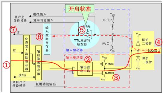
GPIO's push-pull output mode is based on the open-drain output mode. After the "output control circuit", a P-MOS transistor is added.
When the CPU outputs logic "1", the P-MOS tube at number 3 is turned on, and the lower N-MOS tube is turned off to achieve the output high level.
When the CPU outputs a logic “0â€, the P-MOS transistor at number 3 is turned off, and the lower N-MOS transistor is turned on to achieve the purpose of outputting a low level.
In this mode, the CPU can still read the signal of the IO port voltage change from the "input data register".
GPIO open-drain multiplexing output _AF_OD mode works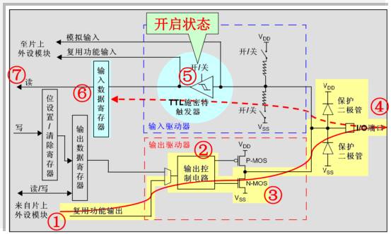
GPIO's open-drain multiplexed output mode works in much the same way as open-drain output mode
The difference is that the source of the input number 2 is different, it is connected to the output of the multiplexing function.
At this time, the "output data register" is disconnected by the output channel.
From the above figure, we can also see that the CPU can also read the level signal from the "input data register" to the external IO port change.
GPIO push-pull multiplexed output _AF_PP mode works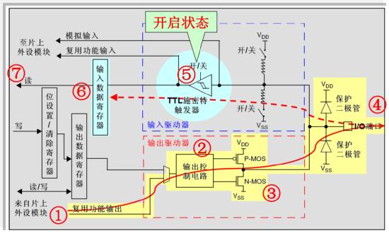
Finally, let's talk about how GPIO push-pull multiplexed output mode works.
No. 2 "Output control circuit" input is connected to the output of the multiplexing function
At this point, the "output data register" is disconnected from the output channel, and the output signal of the on-chip peripheral is directly connected to the input of the "output control circuit".
After we configure the GPIO as a multiplexed output function, if the corresponding peripheral module is not activated, then the output of the IO port will be undefined.
The other parts of the principle are the same as the previously described mode, including the same way of reading the "input data register".
Cast Iron LV 3PH Asynchronous Motor
Cast Iron Lv 3Ph Asynchronous Motor,Three Phase Asynchronous Cast Iron Motors,Cast Iron Motors,Cast Iron Electric Motor
Yizheng Beide Material Co., Ltd. , https://www.beidevendor.com
