Multiplexers are also called data selectors. Common classifications include 4 selection 1 data selectors, 8 selection 1 data selectors (74151, 74LS151, 74251, and 74LS152), and 16 selections of 1 data selector (which can be constructed by connecting two 74151s). Multiplexers also include multiplexing of buses, multiplexing of analog signals, etc., and the corresponding devices also have different characteristics and methods of use.
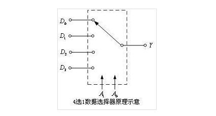
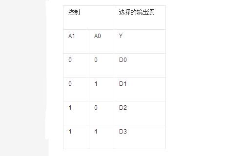
The diagram shows the schematic of a quadruple-select multiplexer. In the figure, D0, D1, D2, and D3 are four data input terminals, Y is an output terminal, and A1 and A0 are address input terminals. As can be seen from the table, using the code that specifies A1A0, any one of four input data D0, D1, D2, and D3 can be selected and sent to the output. Therefore, a data selector can be used to implement multiplexed time-division transmission of data.
In addition, multiplexers are also widely used to generate any combination of logic functions.
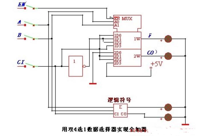
If A1, A0 are regarded as two input logic variables, and D0, D1, D2, and D3 are taken as the different states of the third input logic variable A2 (ie, A2, /A2, 1, or 0), they can be generated. Any combination of three variables A2, A1, A0 that are required for the logic function. It can be seen that a combinational logic function with no more than n +1 input variables can be generated using a multiplexer with an n-bit address input.
Multiplexer Typical ChipA typical mid-range multiplexer has a dual 4-way data selector 74153. Its pinout diagram and logic symbols are shown in Figures 1 (a) and (b).
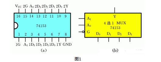
The data selector 74153 includes two 4-way data selectors. Each selector receives four data inputs and generates one output. The two 4-way data selectors share two selection variables. The chip has 16 leads, of which 1D0 to 1D3 and 2D0 to 2D3 are 8 data input lines, A1 and A0 are the selected input lines, 1Y and 2Y are the 2 output lines, 1G and 2G are the enable control terminals, and 1 is the other. Power cord and 1 ground wire.
The output function expression of the 4-way data selector is

In the formula, mi is the smallest item that constitutes a selection variable.
Multiple selector operationThe working principle is that you give A1A0 a set of signals such as 1 0 then it is equivalent to giving him a binary number 2 which is equivalent to strobing the D2 input.
At this time, the output of Y is the signal of D2.
D2 is the output of å•¥Y
In the following example, the transmission of two-digit BCD numbers from A to B is completed and the two numbers can be displayed.
As shown in Figure 1, 2-bit decimal numbers (BCD code) B3B2B1B0 (ten bits) and A3A2A1A0 (ones bits) enter the two data inputs of 74LS157, respectively, and data selection input G1 is connected to a 30-Hz square wave.
When the square wave is at a low level, G1 = 0, the number A (A3A2A1A0) is selected by the multiplexer, and the output from the output is positive, and the 7-segment decoder 74LS48 (output high level active) receives the BCD code and outputs the decoded signal. At the same time sent to the two common cathode seven-segment digital display, two digital display through 74LS139 to control the common cathode terminal level, so that the right digital display A number, the left digital display; when the square wave is high, G1=1 The number B (B3B2B1B0) is sent to the seven-segment decoder by the data selector. At this time, the 74LS139 controls the left digital display to display the B number, while the right digital display does not display. Although the two numbers are displayed alternately, the frequency of the square wave is high and it is visually seen that two numbers are displayed at the same time.
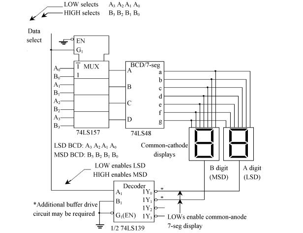
Application of Multiplexer in Long Distance Transmission
It can be seen that due to the use of multiplex selectors, the data transmission originally completed by eight lines in both A and B areas is reduced by half the connection, and a seven-segment decoder is also omitted. When the number of data bits to be transmitted in FIG. 1 is large, more wires and decoders can be omitted by selecting an appropriate data selector.
Galvainzed Steel Pole are mainly used in 15KV and 69KV transmission lines.
Galvanized Steel Pole,Galvanized Pole,Galvanised Steel Posts,Galvanised Shade Sail Pole
Jiangsu Baojuhe Science and Technology Co.,Ltd. , https://www.galvanizedsteelpole.com
