1 micro-step control uNI_rRODE's uc3717 chip is suitable for low-power stepper motor bipolar drive, easy to interface with the microcomputer, its drive circuit is shown in Figure 1.
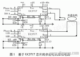
In the figure, l (Bout) and 15 feet (Aout) are respectively connected to the two ends of the phase winding of the stepping motor; 2 feet (T) are connected to the Rc timing component; 3, 14 feet (V.) are the winding coil power supply, Select from 10 V to 45 V; 4, 5, 12, 13 (GND) to ground; 6 (Vcc) is Ic power supply; 7, 9 (I0, I1) are connected to logic level for selecting winding Current; 8 pin (Ph) is the phase input terminal for controlling the rotation direction; 16 pin is connected to the winding current sampling resistor, and the sampling signal is sent to the 10 pin through the Rc low-pass filter to be compared with the reference voltage of the internal voltage comparator; The 11-pin (Vr) is an external reference voltage, and the Vr can be changed to achieve micro-step control. In the full-step, half-step, and 1/4-step modes, Vr is connected to a fixed +5 V.
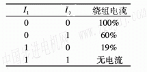
The control of the step size of uc3717 is to select different combinations of I0 and I1 to achieve the purpose of step control. The following table lists the control relationship of the truth table of I0, I1 to the winding current.
The forward current of the two-phase winding is represented by A and B, and the reverse current of the two-phase winding is represented by A and B. The two-phase eight-shot mode of two-phase and single-phase alternating excitation is adopted for the half-step working mode, that is, AB-B- AB→A→AB_→B_→AB_→A. The two-phase energization represents the whole step state, the single-phase energization represents the half-step state, and the 1/4-step working mode is to insert a l/4 step state between the whole step and the half step.
2 position signal pulse detection fixes the incremental photoelectric code disc at the rear end of the motor shaft, the position detecting unit accumulates the number of pulses emitted from the motor coaxial Encoder, and the computer reads the reversible counter data to obtain the actual running distance. Figure 2 shows.
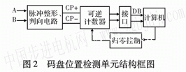
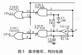
Since the incremental code wheel does not have an initial zero position, to accumulate the number of pulses per block, the computer needs to perform a zero return operation to the up/down counter at the beginning of each block, that is, clear the counter to determine the incremental code disk. The starting position of the axis. The output phase differs by 90 when the code wheel is rotated. The two-way pulse A and B change with the change of the code wheel, and the lead lag relationship between them changes, so that one pulse can be used to strobe the front and rear edges of the other pulse, thereby dividing the forward and reverse counts. Pulse, its pulse shaping, direction discrimination circuit is shown in Figure 3.
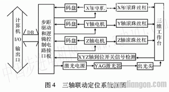
3 three-axis linkage positioning system three-axis linkage positioning system block diagram shown in Figure 4. The position information is output through the computer I/O port and sent to the control circuit to control the motor rotation. The stepping motor is connected by the coupling and the ball screw to drive the three-dimensional table up and down, left and right, and back and forth. The laser head is fixed at the computer control, and the desired track is carved on the workpiece.
In the figure, the x, y, and z axis positioning switch signal detection is three sets of mechanical switches, which are processed into a logic level by a gate circuit on the circuit interface board, and the switch state is determined by cPu, and the three-axis reference system coordinate origin can be determined.
The accuracy of three-dimensional coordinate positioning depends on the accuracy of the information acquired by the detection device. Therefore, further improving the accuracy of the detection device and making it unaffected by the external environment through information compensation will provide a new way to further improve the motion accuracy. To this end, the following measures are taken: the error of the detecting device and its relationship with the state of the system are accurately determined and a mathematical model describing the relationship of the error is established. During the machining process, the numerical control system calculates the error compensation value according to the state information (such as the actual position of the workbench, the temperature of the detection device, etc.) according to the mathematical model, and corrects the measured value of the detection device in real time, thereby ensuring the movement of the moving parts of the machine tool. The respective axes have a high positioning accuracy.
4 Conclusion Laser engraving machine is a fixed point light processing equipment, x, y, z axis start and stop frequently, positioning requirements are fast and accurate. The high-resolution two-phase hybrid stepping motor, combined with micro-step control and photoelectric encoder detection technology, can meet the requirements of fast, stable and accurate positioning of the system. The whole system runs smoothly, has a simple structure, reasonable combination of software and hardware resources, and convenient maintenance.
Encoder
Optical Rotary Sensor,Custom Encoder,Optical Encoder 6Mm Shaft,Handwheel Pulse Generator
Jilin Lander Intelligent Technology Co., Ltd , https://www.landermotor.com
