With the increasing digitization of televisions and the enhancement of functions, TV software upgrades are becoming more and more important, and various TV failures require software upgrades to solve them. At present, the method of upgrading the TV software mainly burns the software into the memory through a special software burner, and then solders the memory to the TV main board; or connects the computer to the TV, and writes the upgrade program to the TV through the computer. Memory. These two TV software upgrade methods have the defects of complicated operation, long time, high cost, and professional knowledge.
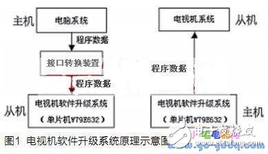
System principleThe principle of the portable TV software upgrade system is shown in Figure 1. The TV software upgrade system is a system that can be operated independently based on the single chip W79E632. Firstly, the system is upgraded as a slave to receive the upgrade program data sent by the computer system and stored, and then the upgrade system is used as a host to send the stored upgrade program data to the television system, and the television system stores and runs the upgrade program data to implement the software. upgrade.

At present, the upgrade interface of the TV is generally a UART serial interface and an I2C interface, and the software upgrade system can be upgraded by using two interfaces. If the computer system does not have these two interfaces, it needs to be connected to the upgrade system through the interface conversion device.
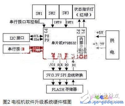
System hardware implementationThe hardware block diagram of the portable TV software upgrade system is shown in Figure 2. The system mainly includes single-chip W79E632, FLASH memory, UART serial interface circuit, I2C interface circuit, interrupt circuit and status indicator.

WINBOND company MCU W79E632 has 128k ISP (In-System Program) FLASH ROM, 4k LD (Loader program) FLASH ROM, software instructions are fully compatible with 51 MCU, high efficiency and fast speed.
W79E632 has UART serial interface, no I2C interface and SPI interface, I/O port P8, P9 analog I2C interface, I/O port P4~P7 analog SPI interface. FLASH storage uses NOR FLASH, 3.3V power supply. Since the FLASH is 3.3V power supply, the W79E632 I/O port level is 5V. To ensure data reliability, the system has a 5V/3.3V SPI bus conversion circuit.
The system's own boot program, initialization program, UART interface data read and write program, I2C interface data read and write program, SPI interface data read and write program are all placed in the internal ROM, FLASH memory is dedicated to store TV upgrade program data. The switches SW2 and SW3 generate low pulses to trigger the external interrupts INT0 and INT1 to control the reception and transmission of the I2C interface data; the serial interface interrupt controls the reception of the UART interface data, and the SW1 generates the low pulse to control the UART interface through the I/O port P3. The transmission of data. The upgrade system uses the W79E632 internal timer and I/O ports P2 and P1 to control the red/green indicator to indicate the current status. For example, the traffic lights are on, the upgrade system is running normally, ready to read and write; the red light is on, the green light is flashing, and the system is upgraded. Writing or reading FLASH memory.
Ningbo Autrends International Trade Co.,Ltd. , https://www.mosvapor.com
