0 Introduction In recent years, image surveillance has become the main method used in the surveillance field. In the past, cable image surveillance systems often faced many problems such as the need to lay a large number of ground and underground equipment lines, high cost, and long construction period. With the rapid development of computer communication technology and network technology, wireless network technology has become a vital component of computer networks. In this context, image transmission wirelessization breaks the unfavorable situation that traditional coaxial cable and optical fiber image surveillance are subject to hardware connection, and has greater flexibility and convenience. A video surveillance system based on wireless network has emerged. The development of wireless video transmission technology has had a profound impact on the architecture and protocols of wireless mobile networks. However, due to the limited bandwidth resources of wireless channels, there are many interference factors, and the amount of video signal data is large, and the real-time requirements are high. Therefore, how to transmit video efficiently in a wireless network environment has become a research hotspot.
This article refers to the address: http://
1 Development Status of Wireless Video Transmission Technology With the development of the information society, people have higher and higher requirements for security monitoring. In addition to centralized party and government organs, enterprises and institutions, such as in the sea, mountains, mines, basements and other complex The environment cannot be used to set up a wired network. All need to achieve security video surveillance, which requires the use of wireless video transmission technology.
At present, most of the wireless video transmission technologies on the market use GPRS and CDMA technologies. The GPRS transmission bandwidth is insufficient, the transmission video only has a few frames per second, and the breakpoint and the wireless reception dead angle are prone to occur in the event of an emergency event. CDMA transmission also has such a drawback that its downlink bandwidth is 153 kb/s and the upstream bandwidth is 70-80 kb/s, so that smooth video transmission is basically impossible. Since the image is only a few frames, it is transmitted in the form of a captured image and is a small screen size. Obviously, this does not meet the real-time application requirements of video surveillance systems. For microwave (digital microwave, spread spectrum microwave), other higher wireless transmission schemes of wireless local area network (WLAN, 802.11 (a.b, g)) and other technologies, which implement video coding with MPEG-2/4, H . 264 and so on. However, most of them have the common problem, that is, they can only achieve through-the-sight transmission, directional transmission, and it is difficult to support mobile transmission, thus limiting the application in the video surveillance system. The structure of the wireless video surveillance system is shown in FIG.

The monitoring system generally uses a low transmission frame rate to ensure the clarity of the transmission, because only the image resolution above CIF of MPEG-4 can meet the needs of investigation and forensics. Therefore, the wireless transmission technology should be fully utilized in the monitoring system, which should be satisfied: it can be applied in non-visible and blocking environments; it is suitable for wireless transmission of real-time images in high-speed mobile; suitable for transmitting high bandwidth and high Code stream, high quality audio and video; excellent anti-interference and anti-fading ability. In practice, there are two main concepts in real-time transmission of wireless video: one is mobile transmission; the other is broadband transmission. Therefore, the development of an infinite video transmission system capable of stabilizing high-definition video with a wide frequency band is one of the key problems that need to be solved. The bandwidth of the infinite link is limited, and this limitation is passed on in mass video. This is especially evident. In this paper, the corresponding research on the fault tolerance of the data transmission mechanism in the wireless video transmission system is carried out, aiming at solving the contradiction between limited bandwidth resources and large amount of video data in wireless video transmission, and fully utilizes the spatio-temporal correlation of video signals to save A waste of bandwidth resources caused by unnecessary retransmissions. The wireless video transmission system is evaluated by utilizing the concept of a bandwidth-distortion cost function. On this basis, the partial retransmission error control mechanism based on the bandwidth-distortion cost minimization criterion is further given, and the bandwidth utilization is improved, and the corresponding experimental analysis is carried out.
2 Wireless video transmission mechanism analysis and fault-tolerant transmission technology The purpose of signal transmission research on reliable channels is to make full use of the bandwidth resources of the channel. For unreliable channels, the research focus in transmission is to make full use of bandwidth resources to achieve reliable transmission, that is, fault tolerance. Transmission technology. The video transmission mechanism on the wireless channel is discussed here, and its main research point is fault-tolerant transmission control. Fault-tolerant transmission control technologies can be classified into three categories according to their control modes: forward error control, feedback-based ARQ, and source channel joint coding. Forward Error Control (FEC) includes channel error correction coding technology, interleaving packing technology and optimized packet scheduling mechanism. The feedback-based ARQ technology includes a Reference Picture Selection (RPS) mechanism using a multi-frame reference mechanism, a hybrid ARQ (Hybrid, HARQ) mechanism, and an ARQ-based feedback error tracking technique. Since the ARQ-based fault-tolerant transmission control technology has excellent performance, the ARQ-related transmission control technology is mainly introduced here, and the shortcomings of the existing video fault-tolerant transmission mechanism are discussed.
Forward error control uses forward error correction coding to overcome channel errors. In the case where the channel error probability fluctuates sharply (such as the existing mobile channel), in order to obtain a certain transmission quality, the forward error correction coding must increase the redundancy check bit according to the worst case of the current estimation, which may result in Waste of bandwidth resources. For a wireless channel with limited bandwidth resources, it is obviously not satisfactory. To this end, consider combining ARQ technology with forward error control, called HARQ technology. There are two types of HARQ: In class I HARQ, the forward coding of the transmitter must have a certain error correction capability. When the receiver finds an error, it first uses the forward error correction coding to correct the error. If the error is corrected, a feedback message (ACK) of the current packet reception success is transmitted to the sender, and a reception failure message (NACK) is sent otherwise. If the sender receives the ACK, it will continue to send the next packet, otherwise, the error packet will be resent. It can be seen that Class I ARQ requires strong forward error correction coding, which results in wasted bandwidth resources in applications with low error rates, but can achieve better throughput than other types of ARQ mechanisms in high error rate environments. effectiveness. In class II ARQ, only forward error correction coding is required to have error detection capability. According to the theory of channel coding error correction capability, this can save bandwidth. When the receiving end finds an error, it sends a retransmission request; the transmitting end only transmits the check code with error correction capability corresponding to the erroneous data. After receiving the receiver, if the error still cannot be corrected, the retransmission request is continued. The sender may choose to retransmit the overall error data and the check code, or may choose to send a stronger error correction capability check code. The control strategy can be adjusted differently. In view of the high wireless channel error rate, wireless transmission with a feedback channel typically employs HARQ-I. Figure 2 shows a wireless video transmission system using HARQ-I. The dashed box in the figure represents the flow of error control in transmission. According to the design principle of HARQ-I, after the receiver finds an error, it first performs forward error correction (the first layer error barrier in the figure). If it cannot be corrected and the current system satisfies the delay limit, it sends an ACK request to make the sender heavy. Pass the data of the error part (the second layer error barrier). Such retransmissions can be repeated until the receiving end receives the correct data or the retransmission delay exceeds the system delay limit. If the correct packet is still not available after the retransmission, the error concealment technique is used at the receiving end to perform error recovery (the third layer error barrier). It can be seen that the basic idea of ​​this mechanism is to use ARQ technology to recover errors after error, so I named it "best effort" ARQ mechanism (BestEffortARQ, BEA, RQ).
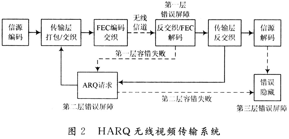
Since the video signal has strong spatio-temporal correlation, and the encoding end cannot completely remove the correlation, the decoding end can use these residual correlations to recover a certain quality video. The quality of the restoration is also closely related to the texture and motion of the recovered part. In general, the restoration effect is better than other cases in the part where the texture is relatively flat and the movement is relatively simple. In this case, if you use BEARQ to retransmit this part of the video, it will obviously cause a waste of bandwidth.
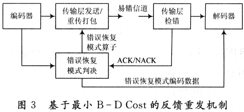
In order to overcome this waste of bandwidth, in practical applications, since the error rate of the channel is closely related to the number of retransmissions, and each retransmission consumes a certain bandwidth, the bandwidth and channel required for successfully transmitting a data packet are required. The error rate is related. Taking this factor into account, the concept of the bandwidth-distortion cost function is used. The core idea is that the reception quality of the terminal video and the bandwidth used in the transmission are not only the video signal under certain packet loss rate, channel bandwidth and transmission delay constraints. The rate distortion performance of the source is related, and is also related to the channel's error rate (loss rate) and terminal error recovery techniques. Use it as a guideline for measuring whether a video package should be retransmitted. On this basis, an optimized end-to-end transmission mechanism is adopted. In this mechanism, the error recovery mode of each part is determined in advance according to the current channel condition and the error concealment algorithm used by the decoding end, and the decoding end is based on the mode information. To decide whether to take ARQ or error recovery. In this way, the waste of bandwidth resources caused by unnecessary retransmission is effectively avoided, and the system bandwidth usage efficiency is improved.
In this paper, a Bandwidth-Distortion (BD) model for lossy channel video transmission is proposed. This model is a dual model in which the RD model considers channel errors and has a similar form to RD. A video transmission system, its performance is mainly measured in two aspects: throughput efficiency and receiver reconstruction distortion. For throughput efficiency, the form is expressed as follows:
η=rs/Bs (1)
Where: rs represents the bit obtained by the source coding; Bs represents the bandwidth resource actually used to successfully transmit the rs bit source data. For a frame-encoded video image, the source coded bits have been determined, so the throughput efficiency in equation (1) will only depend on the bandwidth resource Bs consumed. Reconstruction distortion at the receiving end, due to the possibility of retransmission and post-processing recovery after the transmission error, the final distortion will depend on the channel itself. For the relationship between throughput efficiency and receiver reconstruction distortion, the following relations can theoretically be obtained: 
Where: ds represents the distortion received by the final terminal; ds represents the source coding distortion. 
Where: Pr(·) represents the probability size; p is the average packet loss rate at a certain moment of the channel. Equation (2) illustrates that for any channel with an error rate less than 1, the terminal can achieve error-free reception as long as the bandwidth resources (including the allowable delay) are large enough. Equation (3) shows that under the premise of a certain error rate p and a certain transmission mechanism, the terminal receiving distortion and the bandwidth consumed are inversely increasing. For video transmission systems, the main goal of optimization is to maximize the throughput while minimizing terminal distortion. From the analysis of the above two aspects, it can be seen that these two aspects are increasing in proportion. Obviously, considering that neither of them can achieve optimal transmission performance, it is necessary to provide a new evaluation method to trade off the relationship between them. Based on the above analysis, the BD cost function is used to integrate the above two factors to evaluate the video transmission system. The corresponding BD relationship can be expressed as: 
Where: γ, σ is the statistic associated with the source itself, which can be considered constant for a particular video image. The image is encoded according to the stepwise fine coding method in the ideal sense. The ideal here means that the bit stream is sorted from high to low according to the importance of the rate distortion performance, and the truncation is satisfied with the ideal rate distortion relationship, namely: 
Where: di is the distortion of the reconstructed image obtained after the ri bit is decoded. Without loss of generality, it is assumed that the compressed image data is transmitted according to packets of equal size. For a channel at a certain time, the packet loss rate of each packet is p, and the average number of retransmissions of one packet can be calculated as: 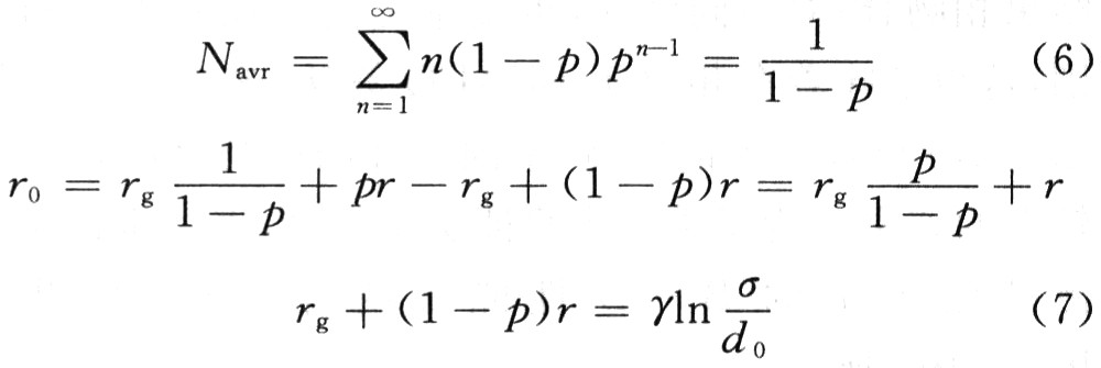
Where: rg is the number of bits indicating that the wrong part is correctly retransmitted to the receiving end. When r0 ≥ (1 - p) r + pr / (1 - p), all the erroneous bits are retransmitted, so the terminal reception distortion is equal to the coding end distortion. Otherwise, according to the two relations in equation (7), the expression (5) of d0 with respect to r0 can be obtained. After establishing the above relationship, combined with the relevant fault-tolerant platform, a feedback retransmission mechanism based on BD Cost is designed. The block diagram is shown in Figure 3.
3 Wireless transmission fault-tolerant control mechanism performance test analysis For the retransmission mechanism and algorithm principle proposed in the previous section, for the convenience of evaluation, without loss of generality, it is assumed in the experiment that the maximum number of retransmissions is 1. As can be seen from the above, the more retransmissions are allowed, the worse the BEARQ mechanism will be from the BD performance for the same terminal reception distortion, and the retransmission mechanism designed here is also improved compared to the BEARQ BD performance. The more obvious it is.
In order to evaluate the performance of the algorithm more comprehensively, the performance of this chapter is tested for different test sequences under the same packet loss rate. Considering the complexity of the texture of the sequence and the intensity of the motion that affect the performance of the algorithm in this chapter. Here, the Foreman sequence with more intense motion but relatively simple texture is used, and the mobile phone with higher texture complexity and the lower motion Akiyo sequence are used as the evaluation sequence. Table 1 is the statistics of the first 100 frames in the case where the three test sequences have QP=14, 16, 20, 22 and the packet loss rate is 3%. The number of error slices is 24, and the total number of error macroblocks is 24×11=264. Let NMB=264, according to the mode decision result, the statistics of the retransmission rate can be obtained.

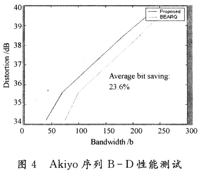
It can be seen from Table 1 that for the same sequence, the retransmission rate is different under different QPs (that is, different code rate), and the larger the QP, the retransmission rate is decreasing, which is lower than the previous experiment. In the case of good performance, the results are consistent; for different sequences, there is a big difference between the retransmission rates, which also means that the proposed mechanism is improved in BD performance compared to the BEARQ algorithm. There is a big difference between the sequences. In order to further verify the experimental conclusions, statistical analysis was performed on the BD performance under the test results, and the results are shown in FIGS. 4 to 6.
 |
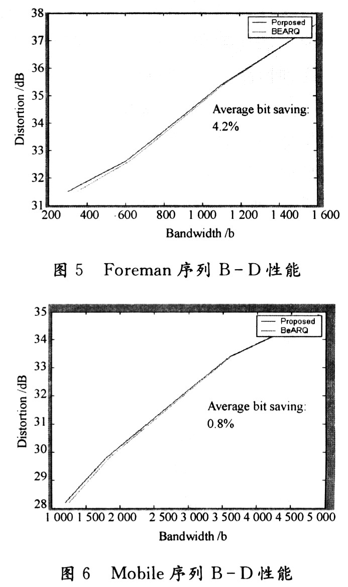 |
Comparing Fig. 4 to Fig. 6, it can be seen that for the Akiyo sequence with low degree of motion and relatively flat texture, the ABQ mechanism is relatively best, and the mechanism of this paper can save more than 20% in the case of 3% packet loss. bandwidth. For the Foreman sequence, which is more intense, it can only save 4% of the bandwidth. For Mobile sequences with complex textures, the algorithm in this paper saves less than 1% bandwidth compared to BEARQ. From the retransmission rate in Table 1 and the correspondence between FIGS. 4 and 6, it is easy to see that the higher the retransmission rate, the lower the degree of improvement in the corresponding BD performance. Therefore, it can be said that the experimental simulation shows that the transmission control algorithm proposed in this paper can effectively reduce the bandwidth used for transmission while ensuring the quality of video reception.
4 Conclusion Here, the performance test and evaluation of the proposed wireless video surveillance transmission mechanism. It can be seen from the experimental results that compared with other methods, the mechanism can effectively reduce the bandwidth required for transmission while ensuring that the receiving quality of the terminal is basically unchanged. In addition, it can be seen from the test results of different sequences that the proposed mechanism is more effective for the transmission of sequences with relatively smooth motion and relatively simple texture, especially in wireless video transmission where bandwidth is severely limited. In addition, the proposed algorithm is an open framework algorithm, and the performance improvement of other fault-tolerant algorithms will further improve the performance of the algorithm. The downside is that only the transmission of the compressed code stream is considered, and the coding end control is not integrated. Therefore, on the whole, the mechanism proposed here is still a partial optimization. Further research is needed on the joint optimization of source-channel-one transmission by further utilizing the proposed BD concept and relational expression.
Dc Contactor,Special Contactor For Soft Starter,Latch Type Contactor,High Voltage Contactor
NanJing QUANNING electric Co.,Ltd , https://www.quanningtrading.com
