Touch screen, also known as "touch screen" or "touch panel", is an inductive liquid crystal display device that can receive input signals such as contacts, when touched on the on-screen graphic button, on the screen The haptic feedback system can drive various connection devices according to a pre-programmed program, and can be used to replace the mechanical button panel and create a live-action audio and video effect through the liquid crystal display screen.
MCGS industrial control configuration software featuresAs a new type of computer input device, touch screen is the most simple, convenient and natural human-computer interaction method. The touch screen is often used in conjunction with the PLC, which can replace the main electrical appliances such as buttons and switches in the contactor-relay control system, and can also replace the output devices such as indicator lights, meters, and digital displays. Not only can it simplify the wiring, but the reliability of the work is greatly improved. The production of the touch screen screen is achieved by means of the following software.
MCGS full Chinese industrial automation control configuration software (referred to as MCGS industrial control configuration software or MCGS) is a set of 32-bit industrial control configuration software, can be stably run on Windows95/98/Me/NT/2000 and other operating systems, set animation Display, process control, data acquisition, device control and output, network data transmission, hot standby, engineering reports, data and curves, and many other powerful functions, and support many data acquisition and output devices at home and abroad.
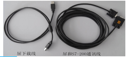
MCGS configuration software touch screen simple use step 1, software installationFind the corresponding folder, run the SETUP.EXE inside, all the default settings, until the completion, plug in the TPC7062KS USB download line, automatically install the driver. Connect the touch screen to the PLC. In the YL-235A, the touch screen is directly connected to the programming port of the PLC through the COM port. The communication cable used is a PC-PPI cable, as shown in the figure below.
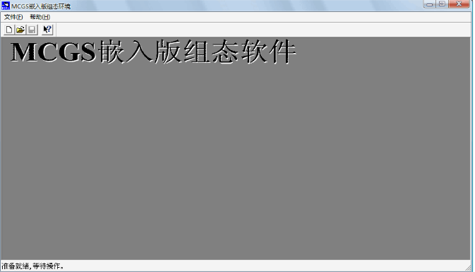
2. Open the software icon on the desktop, the interface is as follows:
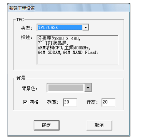
Click New
Press OK
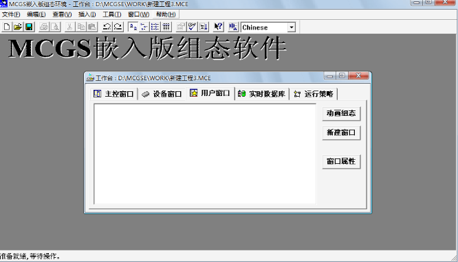
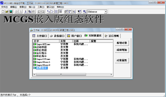
In the real-time database, add objects, double-click the name, you can modify the properties, as shown below, we add five here, respectively, start button, stop button, run indication, stop indication, alarm indication.
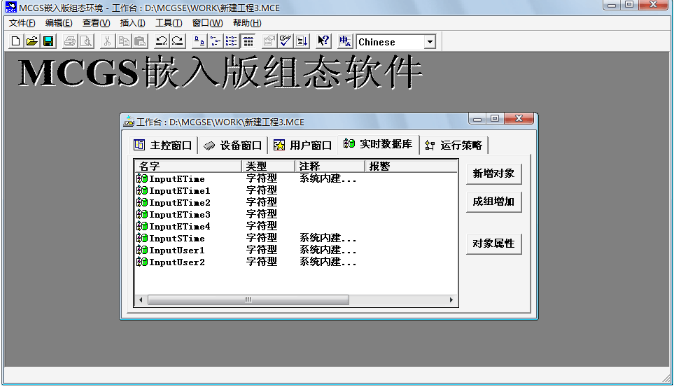
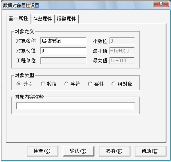
Finally complete the following diagram
3. Double-click the device window of the device window.
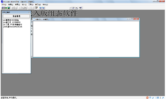
Will double click on the left universal serial port parent device and Siemens s7-200ppi
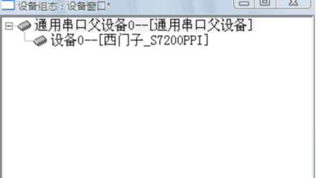
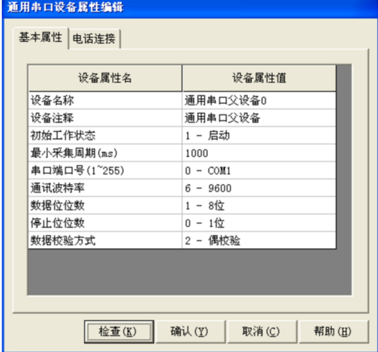
Double-click the universal serial port parent device 0 to set the properties.
â– The serial port number (1~255) is set to: 0 - COM1;
â– The communication baud rate is set to: 6-9600;
â– The number of data bits is set to: 1-8;
â– The number of stop bits is set to: 0-1;
■The data verification mode is set to: 2 – even parity;
â– Other settings are default.
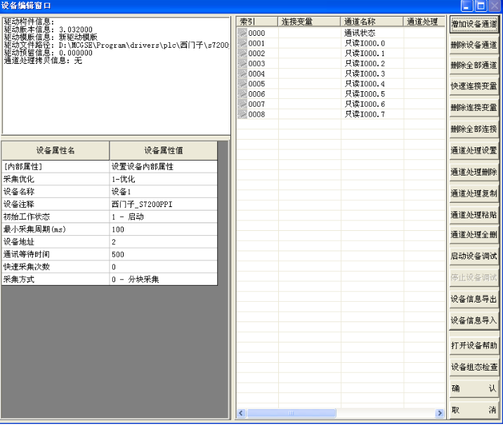
Double-click "Siemens_S7200PPI" to enter the device editing window, as shown below. The default right window automatically produces the channel name I000.0—I000.7, which can be deleted by clicking the “Delete All Channels†button.
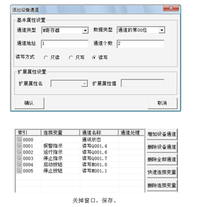
Next, connect the variables. Here, the "start button" variable is used as an example. 1 Click the “Add Device Channel†button and the window shown below will appear. The parameter settings are as follows:
â– Channel type: M register;
â– Data Type: Bit 00 of the channel
â– Channel address: 1;
â– Number of channels: 2;
â– Read and write mode: read and write.
2 Click the "OK" button to complete the basic property settings.
3 Double-click the connection variable corresponding to the "Read-only M001.0" channel and select the variable from the data center: "Start button". In the same way, add other channels, connect variables, as shown in the figure, click the "confirm" button.
Create two new windows in the user window, named as welcome and control windows in the window properties, you can modify the background color.
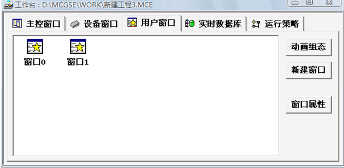
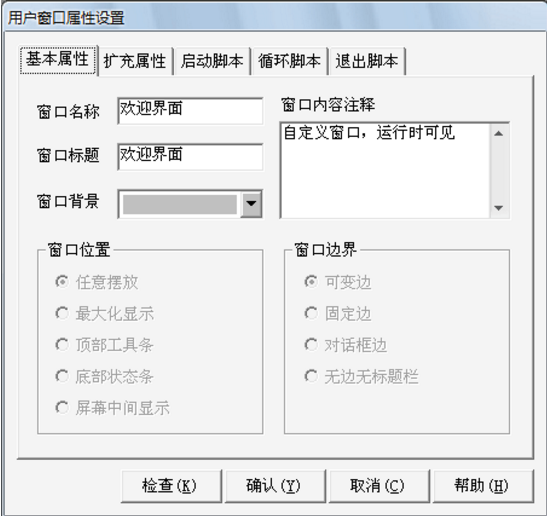
Double click on the newly created window to edit
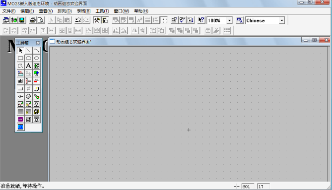
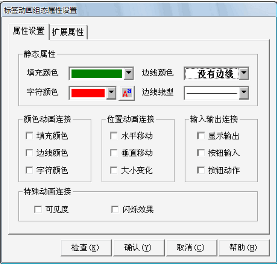
Click on the A in the toolbox to make the label.
Double-click the finished label to perform the property settings.
Open the drawing toolbox by clicking the Toolbox button in the toolbar. Pull out a piece of area on the window, select it, and load the bitmap.
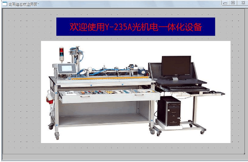
Double click on the picture and make the following settings
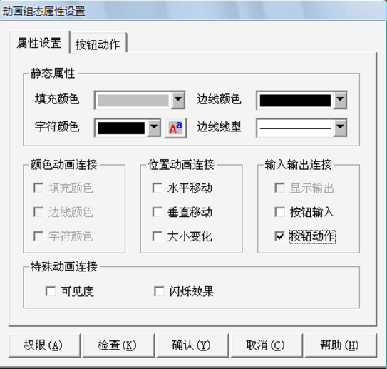
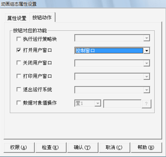
Double click on the control window to enter the window editor
Click the Toolbox button in the toolbar
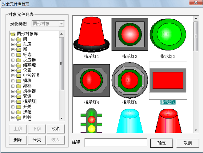
In the data object, click the “?†button in the right corner to select the “Alarm Indication†variable from the data center. In the animation connection, click "fill color", the right side appears, the "〉" button clicks the "〉" button, the following dialog box appears.
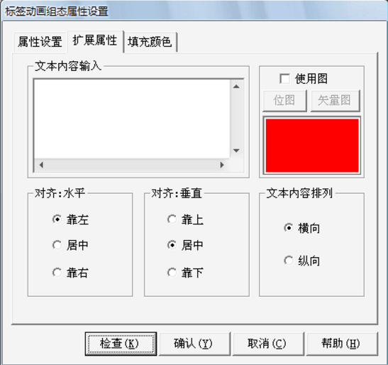
In the Property Settings page, the fill color: white;
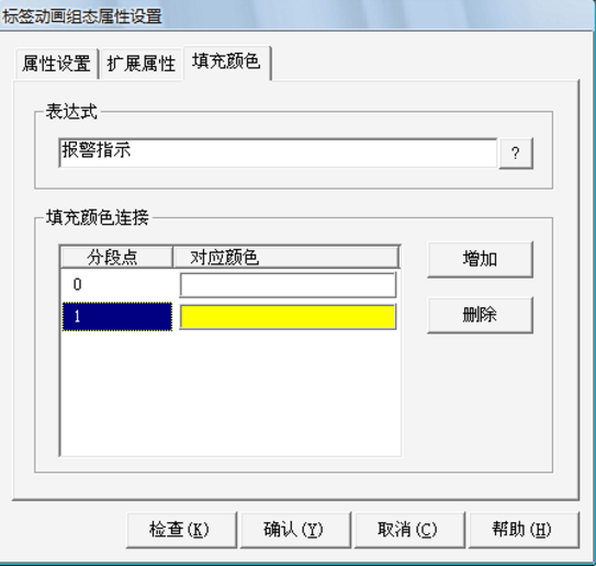
In the Fill Color page, the segment point 0 corresponds to the color: white; the segment point 1 corresponds to the color: light green. See the figure, click the "confirm" button to complete.
The "stop indication" is created as above, and the properties are set as follows:
â– Fill color: white;
â– Expression: stop indication;
â– Segment point 0 corresponds to the color: white; segment point 1 corresponds to the color: red.
The "Run Instructions" property is set as follows:
â– Fill color: white;
â– expression: running instructions;
The segment point 0 corresponds to the color: white; the segment point 1 corresponds to the color: green.
Blink button. Take the start button as an example, give instructions:
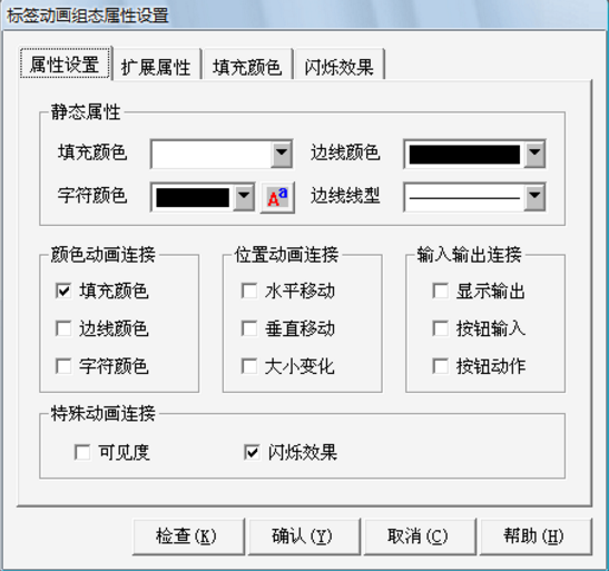
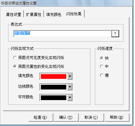
1 Click the Ҡicon in the drawing toolbox, drag out a button of the appropriate size in the window, double-click the button, the following window appears, the property settings are as follows:
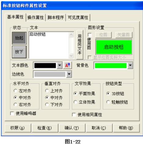
2 In the "Basic Properties" page, the text is set to the start button whether it is raised or pressed; the "lift function" property sets the font for the font, the font size is set to small size 4, and the background color is set to light green; "Press function" is: the font size is set to small five, and the other functions are the same.
3 In the “Operation Properties†page, the lifting function: Data object value operation press 1 to release 0, start button; 4 other default. Click the "OK" button to finish.
5 “Stop button†except the variable connection, text text set to “stop buttonâ€, text color is red, other attribute settings are the same as “start buttonâ€
6 The “Exit Home Screen†button property settings are as follows:
â– Text setting: Exit the main screen;
â– Lift function attribute: the font setting is Song, the font size is set to small size 4, and the background color is set to yellow;
â– Lift function attribute: the font size is set to small five, and the other lifting function;
In the "Operation Properties" page, the lifting function: open the user window and select the "Welcome Screen" making button.
Armor Phone Case,Back Cover Phone Case For Iphone,Phone Case For Tecno For Ifinix,Shockproof Tpu Phone Case
Guangzhou Jiaqi International Trade Co., Ltd , https://www.make-case.com
