A microgrid is a system composed of a micro power supply and a load. Compared to a large power grid, a microgrid appears as a single controlled unit. With the increasing safety and reliability requirements of power users and the diversified power supply requirements, microgrids have gradually gained attention and have been rapidly developed in recent years. However, in the microgrid, due to the special nature of the micro-power supply and the power quality problem caused by the non-linear load, a reasonable method is needed to improve, and the active filter can do this well. The active power filter is a power electronic device for dynamically suppressing harmonics and compensating for reactive power. It is recognized as the most effective means to control grid harmonics, compensate reactive power, and improve grid power quality. The ip-iq method based on the three-phase instantaneous reactive power theory is one of the commonly used harmonic detection methods for active power filters. In this paper, the control method of active power filter is proposed by analyzing the ip-iq method, and the application in the microgrid is simulated in SIMULINK, and satisfactory results are obtained.
1 Harmonic detection principle
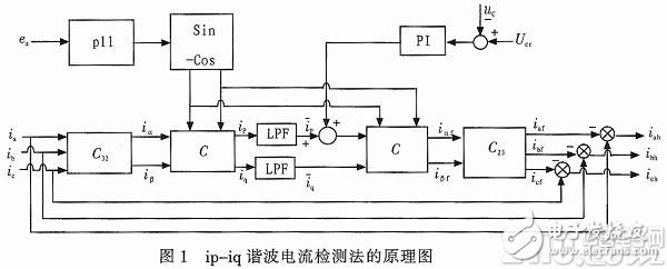
The three-phase instantaneous reactive power theory was first proposed by Akagi Wentai in 1983, and has been continuously researched and improved since then. The ip-iq method is the theoretical system based on this. The basic principle is shown in Figure 1.
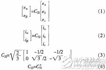
Let the instantaneous values ​​of the voltage and current of each phase of the three-phase circuit be ea, eb, ec and ia, ib, ic, respectively. By transforming it into the α-β two-phase orthogonal coordinate system through the Clarke transform, the two-phase instantaneous voltage and current eα, eβ and iα, iβ can be obtained.
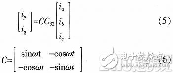
The ip-iq method is shown in Fig. 1. It is necessary to use a sinusoidal signal sinωt and a corresponding cosine signal cosωt which are in phase with the phase a grid voltage, which are obtained by a PLL phase locked loop and a sine and cosine signal generating circuit. At this point, you can calculate ip, iq.
By passing through the low-pass filter LPF, the DC component in ip, iq can be obtained, and the fundamental component of the source current can be calculated, and the fundamental component can be subtracted from the source current to calculate the harmonic component.
2 Parallel active power filter working principle and control method
2.1 Basic principles
2 is a schematic diagram of a parallel APF of an application and a microgrid. As can be seen, the APF mainly has a main circuit, a command current operation circuit, a current tracking control circuit, and a drive circuit. The main circuit is an inverter circuit controlled by PWM. The detection current is calculated by the command circuit to generate the command current. The control circuit calculates the control signal required by the main circuit, and the drive circuit acts on the main circuit to generate the compensation current.
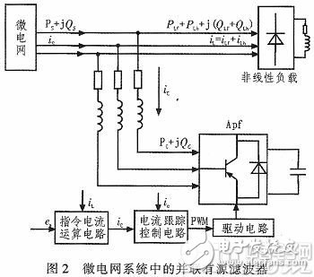
The nonlinear load will be distorted during operation and generate harmonic current. When the parallel APF is not connected to the system, the grid current is equal to the load current:
Is=iL=iLf+iLh (7)
After the parallel APF is connected to the system, the filter detects the load current through the command current calculation circuit and detects the extracted compensation current finger signal, and generates a control signal through the current control circuit to control the APF to issue a suitable compensation current to cancel the harmonic current on the power supply side. Component, ie:
Is=iL+ic=iLf+iLh+ic (8)
2.2 Hysteresis control
Hysteresis control is now widely used in active filters. The basic principle is shown in Figure 3. Comparing the command signal calculated by the command current calculation circuit with the actual compensation current signal, and using the deviation amount of the two as the input of the hysteresis comparator, when the error exceeds the given loop width, changing the switch state of the APF main circuit switch tube, Thereby reducing the error of the compensation current and achieving the purpose of controlling the current.
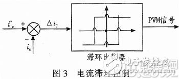
When hysteresis control is used, the choice of loop width has a large influence on the followability of the compensation current. When the loop width is large, the switching tube switching frequency is low, but the following error is large, and the compensation effect is slightly poor. Conversely, when the loop width is small, although the following error will be small, the switching frequency of the switch tube is higher.
2.3 DC side voltage control
For the parallel APF, in the normal operation, in order to ensure its good compensation current followability, the DC side capacitor voltage should remain basically unchanged.
The control of the DC side voltage Uc is shown in the upper right part of Fig. 1, Ucr is the given value of Uc, and the difference between the two is obtained by the PI controller to obtain an adjustment signal, which is superimposed on the DC component of the instantaneous active current. The command signal generated by the time operation circuit contains a certain fundamental active current. Through the hysteresis control, the compensation current generated by the APF contains a certain fundamental active current component, thereby causing energy exchange between the AC side and the DC side of the APF. And then adjust Uc to a given value.
3 Simulation and analysis
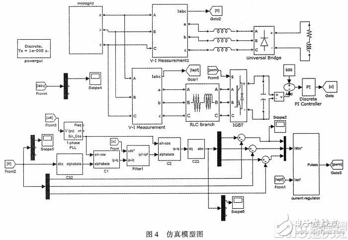
The microgrid model with parallel APF is built in MATLAB/simulink environment as shown in Figure 4.
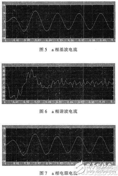
Set the simulation time to 0.1 s and run the simulation model. The simulation results are shown below.
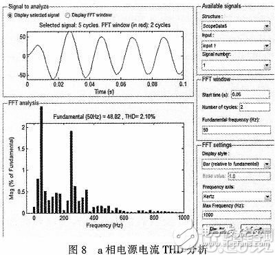
As shown in Fig. 5, the fundamental current of phase a detected by the ip-iq method is shown in Fig. 6. It can be seen that the fundamental current shown in Figure 5 has a good sinusoidality, and it can be seen that the ip-iq method can accurately measure the fundamental current of the microgrid. The a-phase power supply current of the microgrid filtered by parallel APF is shown in Fig. 7. Compared with the fundamental current in Fig. 5, the parallel APF can effectively filter the harmonic current generated by the linear load. Figure 8 shows the THD analysis of the a-phase power supply current through the FFT module in simulink. As can be seen, after parallel APF filtering, the power supply current THD is only 2.10%, and the power quality is improved.
4 Conclusion
This paper mainly analyzes the basic principle and control method of parallel active power filter based on ip-iq method, and establishes the basic model applied to micro-electric enthalpy, and simulates it by MATLAB/simulink. The simulation results show that The parallel active power filter can effectively filter the harmonic current in the microgrid and improve the power quality of the microgrid.
Kadena (KDA) is a hybrid blockchain network and smart contract platform that aims to unite public applications, private blockchains, and other interoperable chains in one place, driving traffic to the high-bandwidth computer at the heart of the Kadena public chain. Kadena`s mining algorithm is Blake2S, which supports ASIC mining.
Kadena is a blockchain network and smart contract token aiming to bring together both public applications and private blockchain.
The coin solves various problems that prevent blockchain adoption on a bigger scale. The protocol enables businesses and developers to make transactions and share information across many networks.
The Coin is actually on the grid to reduce users` experience in the network. Ethereum users experience a lot of network congestion which results in high gas fees.
A few changes have come into Kadena mining. A proof of work blockchain uses PACT to create smart contracts in the hidden gen. Therefore you need to know the following before mining Kadena. PACT is an intelligent contract language serving the needs of the blockchain community.
1.You Need an Excellent Mining Hardware
To mine efficiently, you will require suitable mining hardware. Kadena uses ASIC miners. But, unfortunately for Kadena miners, CPUs and GPUs are not usable. Furthermore, ASIC mining receives support from the Blake2S algorithm.
2.Make Sure You Have a Kadena Wallet Address
You will need a Kadena wallet address to receive and monitor your profit. F2pool also makes the distribution of the revenues to every user daily at 2KDA. The Kadena node wallet is a perfect wallet where you can receive your mined KDA. all you need to do is install it, click receive, and have a new wallet address.
You will need to configure your Asic Miner to a mining pool server for your hashrate and profit to be recorded and monitored.
3.Start Mining
After all the setting is done, your miner will be ready to work. Make sure you enter your wallet address and click on the go button to receive your revenue.
Kda Miner,Antminer Ka3 166Th,Bitmain Antminer Ka3 166Th,Antminer Bitmain Ka3
Shenzhen YLHM Technology Co., Ltd. , https://www.hkcryptominer.com
