The control circuit diagram drawn in electrical technology is a schematic diagram. The actual position and structure of the electrical are not taken into account when drawing the electrical schematic, but the following principles must be observed:
1. When drawing the electrical schematic, you must use the electrician graphic symbols and text symbols specified by the state.
2. The electrical control circuit consists of two parts: the main circuit (the circuit where the controlled load is located) and the control circuit (the main circuit state).
3. Different parts of the same electrical component (such as contacts and coils of the contactor) are drawn in different circuits according to the function and the connected circuit, but the same text symbols must be marked.
4. The graphical symbols of all electrical components are drawn according to the state of no power or external force.
5. Electrical component parts (such as the core and spring of the contactor) that are not related to the circuit when drawing the electrical schematic are not shown in the control loop.
When designing the electrical control circuit, the circuit is simple, the electrical components are small, and the electrical action is accurate and reliable. 2. When designing the electrical control circuit, multiple electrical components should be avoided in order to switch on the circuit of another electrical device. 3. The rated power of each coil must be guaranteed. It is strictly forbidden to use two coils in series.
Electrical schematic specification:
Antenk PLCC connectors Series Sockets are low profile, thin wall sockets designed to convert plastic leaded chips to a thru-hole PCB format on a .100" centerline grid.Antenk's superior precision stamped contact design provides consistent, high retention contacts for all size chips.

PLCC Connectors -PLCCSockets
A PLCC socket is a component that connects a chip carrier to an electronic circuit via surface-mounting or through-hole technology.
Plastic leaded chip carriers (PLCCs) are used in surface-mount technology where electronic circuits are produced, and components need to be mounted or placed directly onto a printed circuit board (PCB). The chip carrier is placed in a PLCC socket, which is either surface-mounted or features through-hole technology. A specialised tool called a PLCC extractor is needed to remove the chip carrier from the PLCC socket.
What are PLCC sockets used for?
PLCC sockets are used in surface-mount device (SMD) and surface-mount technology (SMT) applications. PLCC sockets made of heavy gauge copper alloy are compatible in high shock / high vibration applications. PLCC sockets made of rolled-leaf copper are useful in low-cost computer applications.
Types of PLCC sockets
The two primary categories of PLCC sockets are:
Surface-mount PLCC sockets, which are used in devices sensitive to heat from the reflow process. These allow for component replacement without redesigning or reworking the entire PCB.
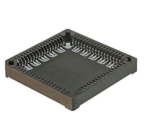
Through-hole technology PLCC sockets are necessary when a device requires stand-alone programming with flash drives or memory devices. These are also beneficial for prototyping activities where wire wrapping is required.
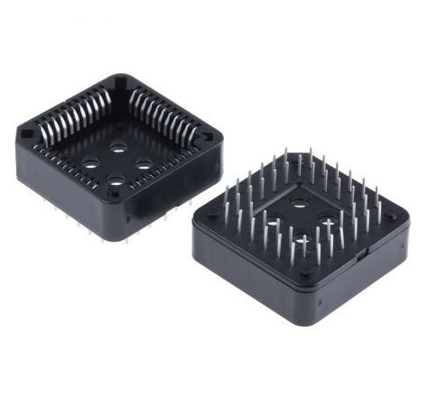
Plcc Socket,Plcc Connector,Plcc Socket Connector,Smd Plcc Connector,PLCC Connector DIP,PLCC Connector SMT
ShenZhen Antenk Electronics Co,Ltd , https://www.antenk.com
