There are many manufacturers of logic analyzers in the market. When choosing logic analyzers, we will pay attention to the comparison of storage depth, sampling rate, protocol decoding, etc., but it is easy to ignore the choice of probes. Here, we will share the probes in the logic analyzer. What plays an important role.
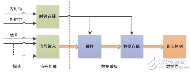
The logic analyzer generally consists of four parts, probe, signal processing, data acquisition, and data display. As shown in Figure 1:

Figure 1 Hardware structure of the portable logic analyzer
The choice of probe is the first step in measuring the signal. Using an inappropriate or poor probe will affect the measurement. Therefore, make sure that the probe has the least impact on the circuit under test.
When selecting and using a logic analyzer, users should pay attention not only to the function of protocol decoding of the host computer software, but also to pay attention to the following aspects.
1.1 Form of measuring line
The measuring lines of the trademarks of different factories are different in style, and the lengths are all about 20cm. There are two kinds of single-ended wires and two shielded wires.

Figure 2 Single-ended wire and shielded wire
Single-ended and shielded line comparison 
1.2 Measurement bandwidth
The manufacturer will give the bandwidth parameters in the instruction manual as shown in the figure below. There is no clear definition of the bandwidth of the logic analysis: According to the author's experience, the bandwidth value depends on the minimum of the asynchronous sampling rate /2, the synchronous sampling rate, and the probe bandwidth.
Bandwidth given by different vendors

Note: In order to accurately measure the signal, it is recommended to select the bandwidth value more than twice the actual measured signal frequency.
A one-foot measuring line of 1 foot (about 25.4 cm) measures the signal within 10 MHz without matching. The introduced measurement error can be neglected. After simple matching, the signal within 30M Hz can be measured.
Taking into account the user's wiring convenience, the domestic logic analyzer LA2000A series uses a single-ended measurement line, and at the same time, the measurement line and the test host are signal matched, which can measure TTL level signals up to 80M Hz.
The measurement line of the LAB7000 series uses shielded measurement lines with an actual bandwidth of up to 670 MHz, which is twice the measurement bandwidth of 250 MHz. This ensures that the signal is acquired without errors.
1.3 Ringing, crosstalk between lines
There are usually multiple input channels for a logic analyzer. When measuring multiple signal lines, the ringing and crosstalk introduced by the measuring line cannot be ignored. As shown in Figure 3, a low frequency square wave signal is subjected to another high speed, high frequency signal crosstalk.

Figure 3 Obvious crosstalk waveform
As a rule of thumb, when testing signals below 10 M Hz, it is not necessary to consider the interference caused by single-ended measuring lines.
The measured signal rate is between 30M and 100M Hz. When using a single-ended measurement line, an abnormal signal may be collected. At this time, the influence of the measuring line should be excluded first, and the shielding line should be selected for measurement.
When the measured signal rate is greater than 100MHz, the user must use the measurement line with the shielding layer and connect the shielding layer to the signal ground. If the shield is not grounded, it will be interfered with by other signals and interfere with other signals as with single-ended lines.
1.4 Probe durability
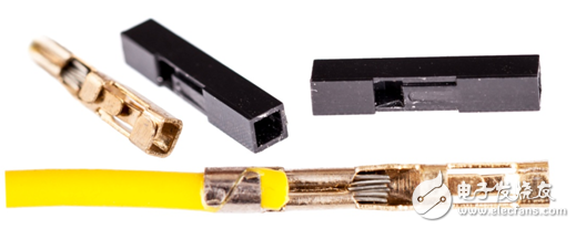
The measuring line consists of a plug and a wire. The common measuring line is composed of DuPont head + 26AWG 7-core tinned wire. DuPont head belongs to stamping parts. The metal reed has poor flexibility. It is prone to looseness and poor contact after repeated insertion and removal. The advantage is that it is cheap and can be easily obtained.

Figure 4 DuPont line plug
The measuring line of the LA2000A series comes standard with a three-layer structure: an insulating plastic sleeve, a one-piece gold-plated copper sleeve, and two high-elastic gold-plated reeds.

Figure 5 ZLG custom 2.54mm plug
The gold-plated reed can effectively form a surface contact with the pin of the signal to be tested, and can ensure a certain reliability after multiple insertions and removals to avoid poor contact. The wire is made of 26AWG 18-core silver-plated copper wire and has good electrical properties. At the same time, the tensile test, the swing test, and the bending test ensure that the wire is not easily damaged and broken.
Counting Module developed for self-service
Communication with deposit system via RS232
Multiple data check to ensure reliable and safe data exchange
Safe and Reliable platform with different sensors to monitor fraud activity
Complete protocal for integration
Software upgrade by USB or RS232
banknote deposit module
Suzhou Ribao Technology Co. Ltd. , https://www.ribaoeurope.com
