The purpose of the system anti-power failure design is to adopt a mechanism to ensure the system's operational status and the integrity of the recorded data in case of accidental loss of power supply; when the system power is restored, the field data can be restored in time. To avoid confusion in the application system. We know that embedded operating systems are increasingly being used in embedded system design and development. Due to the introduction of the operating system, the reading and writing of data is often done by means of files, rather than directly operating on the address of the storage unit. Data is manipulated by means of file reading and writing. During the running of the program, the data is temporarily stored in a volatile storage space, such as SDRAM. Once the system is unexpectedly de-energized, the data is often lost. Therefore, when the system unexpectedly loses power, certain measures must be taken to protect the system from power failure to avoid system confusion. In general, the main idea of ​​the anti-power-down procedure is to generate a power-down signal, capture the power-down signal, process the power-down signal and data, and restore the field state.
If the operating system is not introduced, the data operation is directly performed on the storage unit, and the amount of data per operation is small, and the power-off protection can be performed by means of the interrupt service; while the data operation is performed by the file method, the data amount is generally large, so based on The way to interrupt the service for power-down protection is no longer reliable. The object of this paper is the power-down protection in the design process of the more complex embedded system based on the operating system.
1 System basis for power-down protection scheme
Power-down protection is implemented on the basis of the hardware platform of the ARM system and the μClinux embedded operating system.
The ARM7 family of microprocessors supports eight types of interrupt processing. The external interrupt request is asserted on the external interrupt pin (typically low) and the program status register related bit (ie, the ISR bit of the CPSR) is set to allow the processor response. After the response, the processor enters the interrupt mode of operation, and the PC is loaded with the interrupt vector 0x00000018. In this address unit, the interrupt service routine population address is stored, and the interrupt service routine can be executed. In the power-down protection scheme, the interrupt service routine is very simple, that is, the global variable indicating the power-down is set. This can shorten the program execution time.
Flash memory is a kind of memory that can be electrically erased in the system, and the information is not lost after power. It features low power consumption, large capacity, system-wide programming (programming), erasing, etc., and can be operated by an embedded algorithm to obtain the operation of the chip. A wide range of applications. As a non-volatile memory. Flash is usually used in the system to store program code, constant tables, and some user data that needs to be saved after the system is powered off. The commonly used Flash is 8-bit or 16-bit data width, and the programming Voltage is single 3.3V. Compared with the flash memory, the SDRAM does not have the characteristics of power-down and data retention, but its access speed is much higher than that of the flash memory, and has read. / write attribute, therefore, SDRAM is mainly used in the system as the running space, data and stack area of ​​the program. When the system starts, the CPU first reads the startup code from the reset address 0x0. After the initialization of the system is completed, the program code should be transferred to the SDRAM to improve the running speed of the system, and the system and user stack and operation data. Also put in SDRAM. A SDRAM memory cell can be understood as a capacitor that always tends to discharge. To avoid data loss, it must be periodically refreshed (charged). Therefore, to use SDRAM in the system, the microprocessor is required to have refresh control logic, or a refresh control logic circuit is additionally added to the system. In particular, after the system loses power, an effective mechanism is adopted to ensure sDRAM. The data in is written to F1ash.
2 Hardware design based on power-down protection scheme
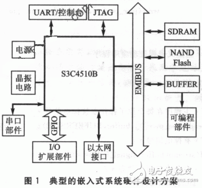
Figure 1 is a typical embedded system hardware design. The system's microprocessor uses the S3c4510B, which is based on the ARM7 architecture. SDRAM is a kind of volatile memory as the running space of the program, similar to the memory of the PC; Flash is non-volatile as the program storage space. The data during the running of the program is often cached in sDRAM, and must be written to Flash when the system loses power.

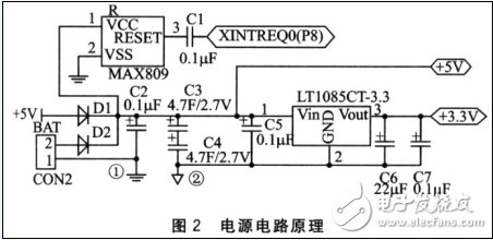
In the system, 5V and 3.3V DC regulated power supplies are required. Among them, S3C4510B and some peripheral devices need 3.3V power supply, and some devices need 5V power supply. In order to simplify the design of the system power supply circuit, the input voltage of the whole system is required to be a high-quality 5V DC regulated power supply. Different from the general power circuit design, the power circuit design of the system has been added with the design of power failure protection. The system power supply circuit containing this design is shown in Figure 2.

In addition to providing 5v and 3.3v power supplies, this power supply circuit provides delay and early warning functions for system power-down protection. The system's power-down protection mechanism can be realized through software cooperation. Under normal circumstances, the entire system is powered by the power supply circuit 1. When the system loses power due to unexpected reasons, the output voltage of the MAX809 module is reversed due to the lowering of the input voltage. The interrupt request is generated by the external interrupt pin XREQ0. The power supply loop 2 is enabled. Through the discharge of large capacitors C3, c4, continue to provide a section of the supply voltage to the system, support the completion of the power-down interrupt service program. The power supply circuit 2 only supplies power to the minimum system and does not supply power to peripheral components that consume large amounts of power. In this way, the minimum system power supply time is long enough to complete the protection of sensitive data.
According to software calculation, the capacitor discharge can be used for the minimum system working time between 0.5~4.5S. This method of calculation is very simple. Write a power-down interrupt service subroutine, this program is just a constant time refresh operation. Similarly, it can be determined by software to erase 2~3MB to Flash during this time. It can be seen that under the condition of adopting this hardware system, the system power-down protection can be reliably guaranteed.
The 18650 (18mm diameter and 65mm length ) battery is a size classification of lithium-ion batteries.
It is the same shape, but a bit larger than a aa battery.
AA batteries by comparison are sometimes called 14500 batteries, because they have a 14mm diameter and 50mm height.
18650 discharge, lc 18650, 19650 battery
Ji'an Powercom New Energy Co., Ltd. , https://www.expowercome.com
