one. Auto-decompression start
Auto-decompression start-up is one of the starting methods for cage induction motors (also known as asynchronous motors). The utility model has the advantages of compact circuit structure, no limitation of the wiring manner of the motor winding, and different transformer voltage taps according to the allowable starting current and the required starting torque, so it is suitable for a motor with a large capacity.
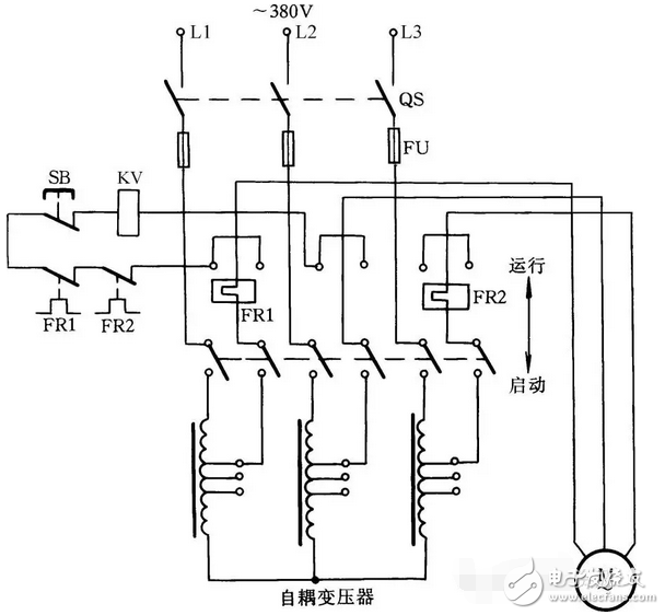
Figure 1 Auto-decompression start
The working principle is shown in Figure 1. When the motor is started, the tool holder is pushed to the starting position, and the three-phase AC power supply is connected to the motor through the autotransformer. After the start is completed, the tool holder is pulled to the running position to cut off the autotransformer, so that the motor is directly connected to the three-phase power supply, and the motor runs normally. At this time, the suction coil KV is electrically attracted, and the shank is held in the operating position by the interlocking mechanism. When you stop, press the SB button.
The autotransformer secondary has a plurality of taps that can output different voltages. Generally, the secondary voltage of the autotransformer is 40%, 65%, 80%, etc. of the primary, which can be selected according to the starting torque.
two. Manual control Y-â–³ step-down start
The Y-â–³ step-down start-up feature is simple and economical. The starting current is 1/3 of the direct start, so it is only suitable for starting the motor under no-load or light load conditions.
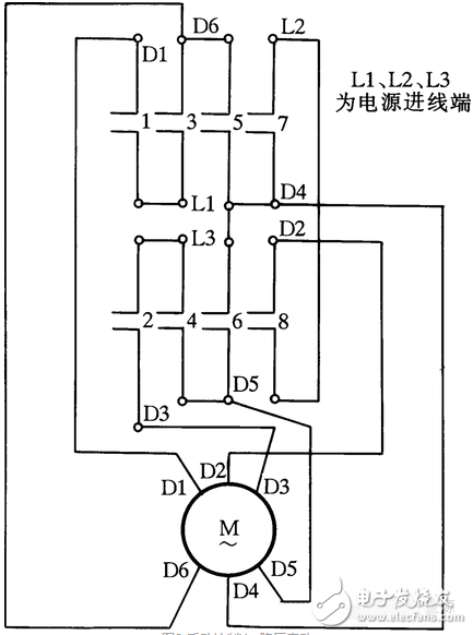
Figure 2 manual control Y-â–³ step-down start
Figure 2 shows the wiring diagram of the QX1 manual Y-△ starter. In the figure, L1, L2 and L3 are connected to the three-phase power supply, and D1, D2, D3, D4, D5 and D6 are connected to the motor. When the handle is pulled to the “0†position, the eight pairs of contacts are disconnected, the motor is not powered off; when the handle is pulled to the “Y†position, the contacts 1, 2, 5, 6, and 8 are closed, 3, 4 7 contacts are disconnected, and the stator winding of the motor is connected to a Y-shaped step-down start; when the motor speed rises to a certain value.
Move the handle to the "â–³" position. At this time, the contacts of 1, 2, 3, 4, 7, and 8 are turned on, the contacts of 5 and 6 are disconnected, and the stator winding of the motor is connected to the â–³ shape for normal operation.
three. Stator winding series resistance start control
When the motor starts, the resistance is connected in series in the stator winding of the motor. Because the voltage drop occurs on the resistor, the voltage applied to the winding of the motor is lower than the power supply voltage. After the start, the resistor is shorted to make the motor run at the rated voltage. The purpose of safe start.
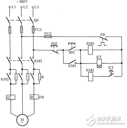
The stator winding series resistance starting control circuit is shown in Figure 3. When the motor is started, the button SB1 is pressed, and the coil of the contactor KM1 is electrically attracted, so that the motor is stepped into the resistor and stepped down. At this time, the time relay KT coil is also energized, and the KT normally open contact is closed after a delay, so that the KM2 coil is electrically connected. The KM2 main contact closes the short-circuit start resistor to operate the motor at full voltage. When the machine is stopped, press the stop button SB2.
four. Manual series resistance start control
When the three-phase AC motor label is marked with a wiring method with a rated voltage of 220/380V (â–³/Y), the Y-â–³ method cannot be used for the step-down start. It can be started by this series resistance or reactor method.
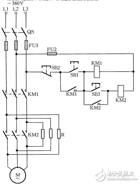
The line is shown in Figure 4. When the motor needs to be started, press the switch button SB1 and the motor series resistor is activated. After the motor speed reaches the rated speed, press SB3 again, and the motor power supply is changed to full voltage power supply to make the motor run normally.
Fives. Stator winding string resistance (or reactance) step-down start another method
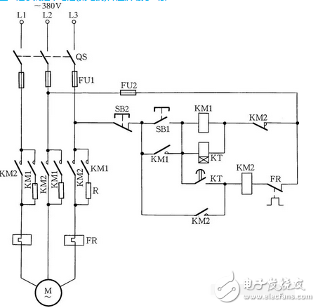
Figure 5: Stator winding string resistance (or reactance) step-down start another method
When the start button SB1 is pressed, KM1 and KT are energized, the normally open auxiliary contact is closed and self-locked, and the stator winding of the motor is stepped into the resistor to start. After the time relay reaches the set time, the KT normally open delay closes the contact closure, KM2 gets the electric action, its main contact closes the short circuit of the resistance, the motor stator winding adds the full voltage of the power supply, and the startup process ends, as shown in Figure 5. .
This type of circuit is suitable for cage-type asynchronous motors that require a smooth start-up medium capacity. The disadvantage is that the starting torque is reduced by the reduction of the starting current. In addition, the starting resistor consumes a certain amount of power, so it is not suitable to start frequently.
six. Automatically convert Y-â–³ start control with transistor delay circuit
The delay circuit composed of electronic components has the advantages of small size and low price. The Y-â–³ start control circuit is automatically converted by the transistor delay circuit as shown in Fig. 6. When the start button SB1 is pressed, the AC contactors KM1 and KM2 are energized at the same time, and the motor is connected to the Y-shaped start. At the same time, the normally open auxiliary contact of the KM1 turns the transistor delay circuit on. The relay KT delays the action, and its normally closed contact KT opens to cut off the coil circuit of KM2; at the same time, its normally open contact KT is closed, so that the contactor KM3 is electrically connected, and the motor is connected to the â–³ shape for normal operation.
Adjusting the capacity of the capacitor C2 in the line or the potentiometer RP can control the time that the transistor reaches conduction, that is, the delay time.
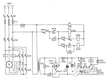
Figure 6 Automatic conversion of Y-â–³ start control with transistor delay circuit
7. Two controls using autotransformer and time relay
The 220/380V â–³/Y-cage type motor with large capacity cannot be started by Y-â–³ method, and the auto-coupling transformer and time relay can be used to complete the automatic control start. As shown in Fig. 7(a), as long as the operation button SB1 is pressed, KM1 pulls in and starts to step down. After a period of time, after the motor reaches the rated speed, the time relay KT operates, KM1 loses power, KM2 is energized, and the motor is at full pressure. Under normal operation. When the SB2 stop button is pressed, the motor loses power and stops. Another circuit using autotransformer and time relay start control is shown in Figure 7(b). Its circuit is perfect, so it is very common to use this method when starting large motors. When the work button is pressed, the start button SB1 is pressed and the motor is stepped down. After the motor is started, the time relay can be automatically converted to full pressure operation. In addition, an indicator line is added to Figure 7(b) to indicate the condition of the entire startup process.
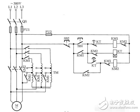
Figure 7 Two controls controlled by an autotransformer and a time relay
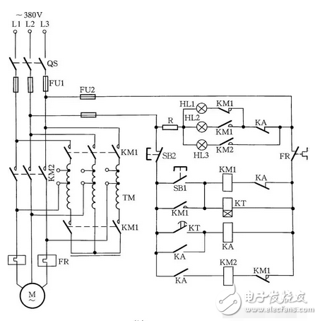
Figure 7 Two controls controlled by an autotransformer and a time relay
Eight. Auto-transformer manual start control
The auto-transformer manual start control circuit is shown in Figure 8. When the motor is started, press the SB1 button. At this time, the KM1 contactor is energized and the motor is started by the autotransformer. After the motor is started, press the SB3 button and the motor will become normal full-pressure operation.
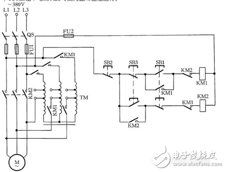
Figure 8 Autotransformer manual start control
nine. Y-â–³ step-down start control with intermediate and time relay delay conversion
This kind of control circuit is designed with a first-level intermediate relay and time relay to prevent the phase-to-phase short circuit caused by the large-capacity motor in the Y-â–³ conversion process due to the short conversion time and the arc cannot be completely extinguished. It is suitable for large-capacity motors with a delta connection of 55kW or more, as shown in Figure 9.
The working principle is: When the power is turned on, the time relay KT2 is energized to prepare for starting. When the start button SB1 is pressed, KM1, KT1, and KM3 are energized. KM1 normally open auxiliary contact closure self-locking, motor winding is connected to Y-connected step-down start. After KT1 reaches the set delay time, the normally closed contact that KT1 delays to open is disconnected, so that KM3 loses power and is released; at the same time, KT1 delays the normally open contact to close, so that the intermediate relay KA is energized. The KA normally closed contact opens to de-energize the KT2 and the KA normally open contact closes. When KT2 is powered off and the delay contact reaches the delay time (0.5~1s), KM2 is energized. At this time, the motor is converted from the Y-connection to the delta connection, and the startup process ends.
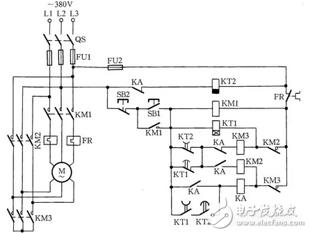
Figure 9 Y-â–³ step-down start control with intermediate and time relay delay conversion
ten. Automatically convert Y-â–³ start control with time relay
Use the time relay to automatically convert the Y-â–³ start motor control circuit as shown in Figure 10. When the button SB1 is pressed, the contactors KM3, KM1 are engaged, and the motor is activated in a Y-shape. After a certain delay, after the motor is started (time relay is generally controlled at 30s), the time relay KT normally closed contact is disconnected, so that KM3 is de-energized, and the KM2 coil is turned on again due to the release of KM3, KM2 Pull in, the motor is changed to â–³-shaped operation.
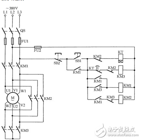
Figure 10 Automatic conversion of Y-â–³ start control with time relay
eleven. Cage motor Y-â–³ switching start control
The line is shown in Figure 11. When starting the motor, first close the switch QS, press the button SB1, the contactor KM1 is electrically connected, and the contactor is self-locking. The Y-shaped start contactor KM3 coil and the time relay KT coil remain energized, the KM3 normally open main contact is turned on, and the motor is connected to the Y-shaped start. At the same time, the normally closed auxiliary contact KM3 is disconnected, so that the delta-shaped running contactor KM2 coil is broken. After the time relay delays to a certain time (the time relay can be adjusted by the capacity of the motor and the load at the start), the normally closed delay split of the time relay KT and the normally open delay closed contact respectively act to make KM3 break. Electric, the KM2 coil is energized, and its contacts are self-locking, and the motor is connected to the delta shape. At the same time, the KM2 normally closed auxiliary contact is disconnected, which causes the KT and KM3 coils to be de-energized.
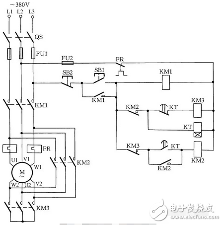
Figure 11 Cage motor Y-â–³ switching start control
In Fig. 11, the thermal relay FR is connected in series with the one-phase winding of the motor, and the setting current should be the rated value of the motor phase current. In the motor of the delta connection method, the thermal relay is connected as described above, which is relatively reliable.
twelve. Manual Y-â–³ step-down start control
In areas with poor conditions, manual Y-â–³ step-down control lines can also be installed, as shown in Figure 12. When the start button SB1 is pressed, KM1 is energized, its normally open contact is closed, KM3 is energized, the normally closed contact is opened, the normally open contact is closed, and the motor winding is connected to a Y-shaped step-down start. When the speed reaches (or is close to) the rated speed, press the SB3 button to release the KM3, the KM2 is electrically connected, and the motor is converted to the delta connection by the Y-connection. This control circuit is suitable for a delta-connected motor of 55 kW or less and 13 kW or more.
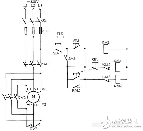
Figure 12 manual Y-â–³ step-down start control
thirteen. Start control using compensator
The line is shown in Figure 13. When the start button SB1 is pressed, the contactor KM1 and the time relay KT are energized, and the KM1 normally open contact is closed and self-locked. The main contact of the contactor KM1 is closed, so that the compensator is connected to the motor step-down starting circuit, and the motor starts to start. The time relay KT is delayed according to the set time. After the motor reaches the running speed, its normally closed contact opens, the contactor KM1 is de-energized, the main contact is opened, the compensator is disengaged, and the normally closed contact is closed. In addition, the time relay KT normally open contact is also turned on. At this time, the contactor KM2 is energized, its normally open contact is closed, the KM2 normally closed contact is opened, the time relay KT is de-energized, and the contactor KM2 is closed. The motor is put into normal operation.
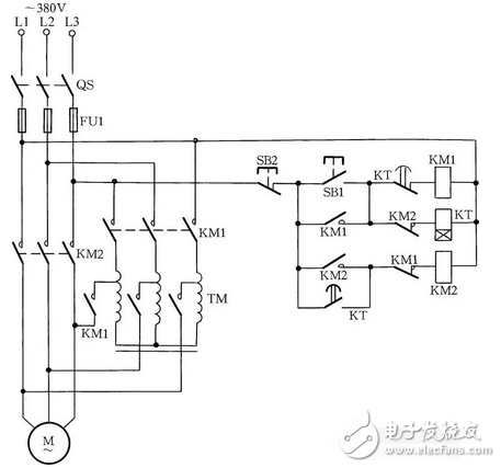
Figure 13 Start control with compensator
fourteen. Y-â–³ step-down start control with two contactors
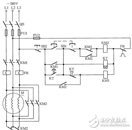
Figure 14 Y-â–³ step-down start control with two contactors
Press the start button SB1, KM1, KT get the electric action, KM1 normally open the auxiliary contact to close the self-locking, and the motor winding is connected to the Y-shaped step-down start. After a period of time, the normally closed contact of the KT delay open is disconnected, KM1 is de-energized, and its normally closed auxiliary contact is closed. At the same time, the normally open contact of KT delay closing is closed, KM2 is energized, its normally closed contact is opened, and the Y-shaped wiring is disconnected; its normally open contact is closed, so that KM1 is energized, and its main circuit is normally open. The contact, the motor is converted from the Y-connection to the delta connection.
This kind of circuit is only suitable for the small-capacity motor with the power of 13kW or less, but the KM2 contactor is normally closed. The auxiliary contact is connected to the main circuit, the capacity is small, and it is easy to burn.
fifteen. Realize Y-â–³ step-down start control with 3 contactors
The Y-Δ step-down control circuit with three contactors is shown in Figure 15. When the start button SB1 is pressed, KM1, KT, and KM3 are energized, and the motor winding is connected to the Y-shaped step-down start. After the time relay reaches the set delay time, the normally open contact of the time delay is closed, the normally closed contact of the timed open is disconnected, and the KM3 is de-energized. At this time, the KM3 normally closed auxiliary contact is closed, so that the KM2 is powered. In the action, the motor winding is converted into a delta connection by the Y-connection method, and the startup process ends.
This control circuit is suitable for a delta-connected motor of 55 kW or less and 13 kW or more.
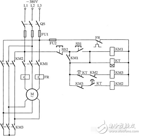
Figure 15 Y-â–³ step-down start control with 3 contactors
sixteen. Commonly used automatic compensation step-down starter cabinet
In the case of automatic control start, XJ01 automatic start compensator is often used, which is mainly composed of autotransformer, AC contactor, intermediate relay, time relay and control button.
The working principle of the XJ01 automatic start compensator is shown in Figure 16(a): When the power is turned on, the light I is on, press the start button SB1, the KM1 coil is energized, the KM1 main contact is closed, and the motor is stepped down. KM1 is closed and self-locking, and lamp II is on. KM1 normally closed contact is open, lamp I is off, KT is energized, its normally open contact is closed, KA coil is energized, normally closed contact KA is disconnected, KM1 is powered off, KM1 normally open contact is open. At the same time, the normally open contact KA is closed, the KM2 coil is energized, the KM2 main contact is closed, the motor is fully pressurized, the KM2 normally open contact is closed, and the lamp III is illuminated.
The larger power motor can also be equipped with a matching power distribution cabinet to meet the starting requirements. Figure 16 (b) shows the line of the 75kW motor starting power distribution cabinet. This type of starter has both an automatic operation function and a manual operation function. When the operation is automatic, the power switch is turned on and the green indicator light is on. When the button switch SB1 is pressed, the KM3 and the time relay KT are electrically connected, and the KM3 normally open contact is closed, the KM2 is also closed, and the SB1 button is released, and the KM3 is self-selected. The lock contacts continue to open the KM3, KM2, KT coil loops and remain engaged. At this time, the power supply voltage is stepped down by the autotransformer and then connected to the motor to make the motor step-down. After a certain period of time, the KT time relay acts to make the KT delay normally open contact closed, and the intermediate relay KA is electrically connected. lock. When the KA is closed, the energized coils of KM3, KM2, and KT are disconnected to release them. At the same time, after the KM3 and KM2 are released, the normally closed contacts are closed, the KM1 contactor is turned on, and the KM1 contactor is put into the motor. State, the motor is running at full pressure. At the same time, the yellow light (start indicator) goes off and the red light (run indicator) lights up. When the motor operation needs to be stopped, the stop button SB2 can be pressed and the motor stops working. The SB3 button in the circuit is a manual direct input button. Its function is that when the time relay fails and cannot be automatically put into operation, the motor such as the automatic button SB1 can be pressed to reach the rated speed close to the synchronous speed, that is, the pointer of the ammeter gradually decreases to near. When the motor is rated for current, press the SB3 button to put the motor into operation. This power distribution cabinet can control a three-phase asynchronous motor of 14~75kW. Fuses, thermal relays, and transformers in the circuit are also used in conjunction with the motor capacity.
For the 90~115kW motor, the XJ011 series can be used to automatically control the auto-coupling decompression starter cabinet. The circuit is shown in Figure 16(c). The working principle is the same as above. Pay attention to the following points when using.
The 1XJ011 series auto-decompression start-up cabinet needs to measure the resistance of the conductor to ground by not less than 1MΩ with a 500V megohmmeter before use, and tighten the joints.
2 When installing, the power cable and load motor cable should be inserted from the bottom of the box. The L1, L2, and L3 calibration wires are connected to the power supply or the pile head on the circuit breaker. The MA, MB, and MC are connected to the three-phase motor.
3 The autotransformer is equipped with a second-speed tap with rated voltage of 65% and 80%. In the application, the position of the tap can be determined according to the size of the load.
4 time relay can be adjusted within the range of 0~60s, and the starting motor time can be adjusted as needed. The rated current of the thermal relay should be set according to the rated current value of the motor.
5 The startup time of the startup cabinet is 10~20s. If the motor has a large capacity and the load is heavy, the maximum start-up time can be adjusted to 25s.
6 If the starter cabinet needs to be operated remotely, it can be connected according to SB1' and SB2' in the circuit diagram.
7 In the process of using the power distribution cabinet, if the thermal relay malfunctions, the operating current of the thermal relay can be adjusted to a larger value; if an overload action occurs, the thermal relay "reset" button must be pressed to continue the use.
8 During the use of the power distribution cabinet, the dust should be removed frequently, and the contact parts of each electrical appliance should be inspected regularly for good contact. If there is any problem, it should be repaired in time.
9 When the contactor is working, if there is noise or delayed release, the armor pole area dust or grease will be wiped clean and it will return to normal.
10 When overhauling the power distribution cabinet, check the contactor contacts for singeing. If the contact is singeed, apply fine lines to trim the contacts.
Large power distribution cabinet starters can also be made by the electrician himself. Generally, a certain size of cabinet can be welded with angle steel and iron sheet. Then, according to the power of the motor, contactors, circuit breakers, autotransformers, transformers and thermal relays with sufficient rated capacity are selected. The power supply extends from top to bottom during installation. That is, the upper pile head is connected to the power source, and the lower pile head is connected to the load. There is enough space between the power supply phases. The autotransformer metal casing, the distribution cabinet bottom casing and the motor metal casing are connected and grounded by grounding wires respectively to ensure electrical operation safety. The assembly is carried out in accordance with the wiring shown in Fig. 16 (d). Its working principle is: at the start, the contactor of the 5 rows of main contacts first acts, turns on the autotransformer, and then the power supply is stepped down by the autotransformer, the supply motor M is started, and the speed is close to the motor itself. At the rated speed, the time relay acts to release the start contactor. After the release, the running contactor KM2 coil circuit is connected through the intermediate relay, so that the 380V voltage is directly connected to the motor M through the suction of the running contactor, and the start is started. End.
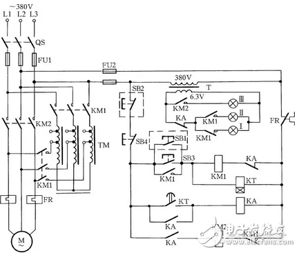
Figure 16 (a) XJ01 automatic start compensator
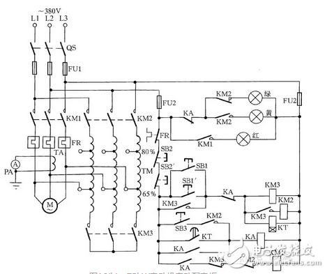
Figure 16 (b) 75kW motor start distribution cabinet
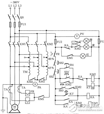
Figure 16 (c) 90~115kW motor XJ011 series
Automatic control auto-decompression starter cabinet
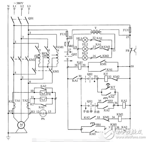
Figure 16 (d) Self-made assembled large automatic compensation step-down starting power distribution cabinet
Seventeen. Frequency sensitive varistor start control
Figure 17 shows the start-up control circuit for a wound-type asynchronous motor using a frequency-sensitive varistor. It works by utilizing the characteristic that the impedance of the frequency sensitive varistor changes significantly with the change of the rotor current frequency.
When the start button SB1 is pressed during startup, KM1 is energized, its normally open auxiliary contact is closed and the motor rotor circuit is connected to the frequency sensitive varistor. When the time relay KT reaches the set time, the normally open contact whose delay is closed is closed, the intermediate relay KA is energized, its normally open contact is closed, KM2 is energized, and the KM2 normally closed contact is opened, so that the time relay When the KT is powered off, the KM2 normally open contact is closed, the frequency sensitive varistor is shorted, and the startup process ends.
The short-circuiting of the component KA is to prevent the thermal relay from malfunctioning due to the long startup time: at startup, the thermal relay is heated by its normally closed contact. After the start, the KA action puts the thermal relay into operation.
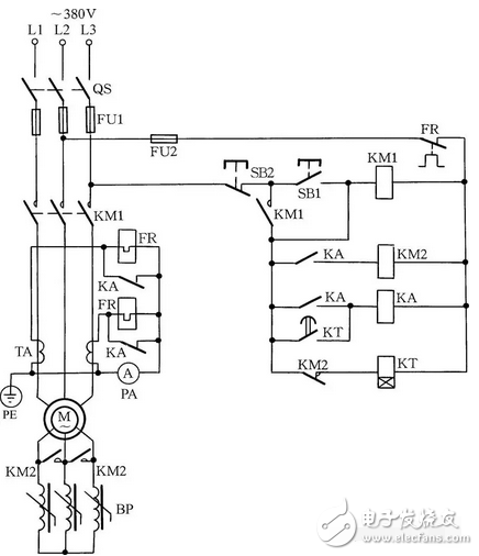
Figure 17 frequency sensitive varistor start control
Eighteen. Yanbian triangle step-down start
The Yanbian triangle step-down starting line is shown in Figure 18. When the start button SB1 is pressed, KM1 is energized, its normally open auxiliary contact is closed and self-locking, KM3 and KT are energized, and the motor winding is connected to the Yanbian triangle to step down. After the KT reaches the set time, the normally closed contact that is delayed to open is disconnected, so that the KM3 is de-energized and the KM3 normally closed auxiliary contact is closed. At the same time, the KT delay closed normally open contact is closed, KM2 is energized, its normally open auxiliary contact is closed and self-locking, and the motor winding is converted from a delta triangle to a delta connection, and the starting process ends. This connection is suitable for applications requiring a large starting torque.
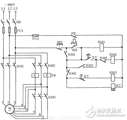
Figure 18 Yanbian Triangle Buck Start
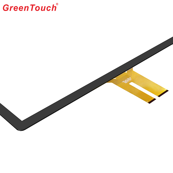
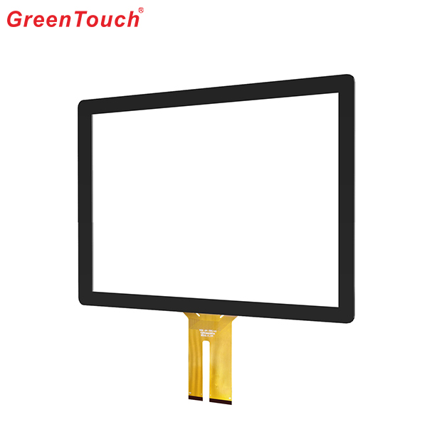
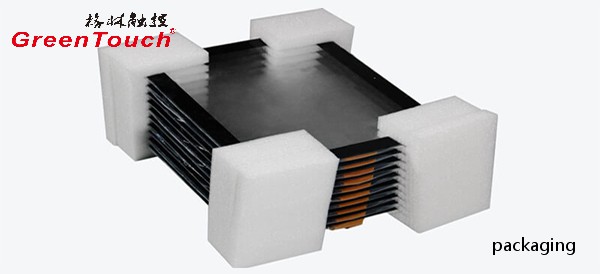
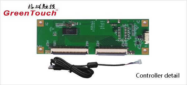
This product response time is shorter than resistive tonch screen's with a good touch.It is widely used to Phone,Tablet,E-book,gaming device by hands holding,Touch Monitor,GPS,All-In-One and so on.GreenTouch projected capacitive touch technology is with fast and sensitive response, the design with frame (without frame is optional) makes it looks professional and generous. The model is designed for high-intensity and high-frequency business environments.
Product show:
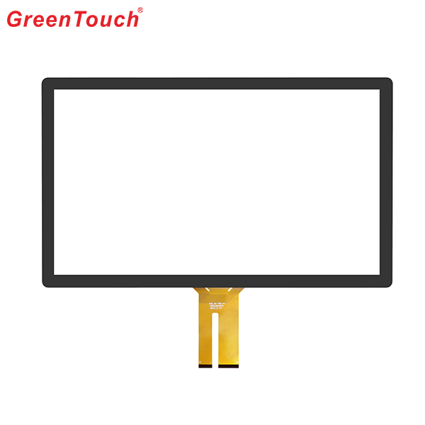
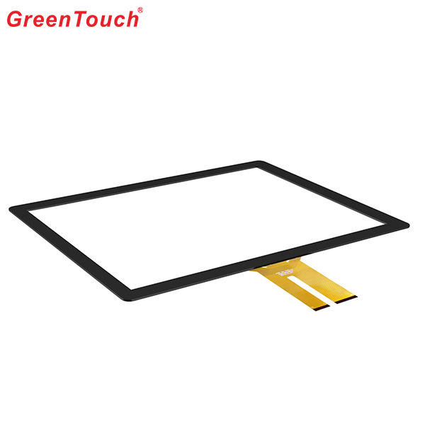
Capacitive Touch Screen Panel,Android Touch Screen,Portable Touch Screen,Pcap Touch Screen,POS Terminal Touch Screen,Mini Capacitive Touch Screen
ShenZhen GreenTouch Technology Co.,Ltd , https://www.bbstouch.com
