introduction
In the daily maintenance, repair, pre-test, etc. of the capacitors in the substation, the capacitor bank and the single capacitor must be discharged before work, because the "Safety Regulations" clearly stipulates that the cables and capacitors should be fully discharged phase by phase before grounding. The neutral point of the star-connected capacitor should be grounded, the series capacitor and the capacitor separated from the whole set of capacitors should be discharged one by one, and the capacitor casing mounted on the insulating bracket should also be discharged. At the same time, the application of power cables and other equipment in power production More and more extensive, power cable daily maintenance, repair, pre-test, etc., must be fully discharged before work. However, during the discharge process, whether the voltage generated by the residual charge is below the safe voltage and whether it has been fully discharged, but there is no special electrical inspection device, and there is no clear indication of whether the cable and capacitor discharge are completed.
1 Overall overview
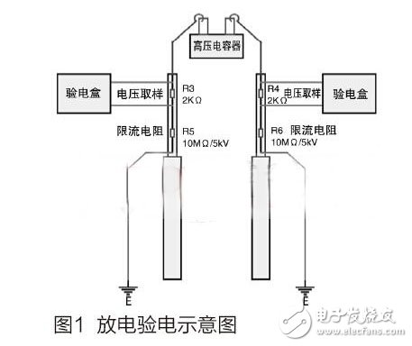
The practical application diagram of the capacitor charged alarm discharge rod is shown in Figure 1. The discharge of the capacitor must be completed by two discharge rods at the same time. The voltage across the high-voltage capacitor is shorted through the ground loop and the two current-limiting resistors. The residual charge on the capacitor is gradually discharged to “0â€. During discharge, the discharge is discharged. A current is applied to the 2kΩ sampling resistor at the high voltage end of the rod to generate a voltage signal, which is sampled, judged and processed by the electroscope.

2 hardware circuit design
The electroscope box is the core component of a capacitor-specific discharge rod with a charged alarm function and is directly used to detect the residual charge of a capacitor or cable.
2.1 Block diagram of the test box
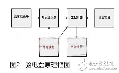
The block diagram of the electroscope box is shown in Figure 2. The high-voltage signal is DC-biased and enters the main controller. The internal battery is used to supply power to the DC bias box main controller. In order to improve measurement accuracy and control flexibility, the design is designed. Instead of adopting the conventional "discrete component + logic chip" circuit method, a small-scale controller is selected, and the A/D converter inside the controller accurately measures the high-voltage signal, while the pin directly drives the indicator light and the bee. The sounder prompts the staff, the device has a self-test function.

4.2Mm Ribbon Connector,Strip Connectors,Strip Terminal,Strip Connector
YUEQING WEIMAI ELECTRONICS CO.,LTD , https://www.weimaiconn.com
