Feedforward noise reduction
The feedforward noise reduction system implements noise reduction by a signal whose headphone output is the same as the ambient noise frequency response but opposite in phase. As shown in Fig. 1, the feedforward microphone detects noise and generates an inverted signal through the filter circuit, and the inverted signal and the noise signal are cancelled at the eardrum, thereby reducing the noise level heard by the human ear. The filter circuit here is mainly used to compensate for the difference between the noise detected at the eardrum and the microphone, and also compensates for the response capability of the speaker itself to the noise canceling signal.
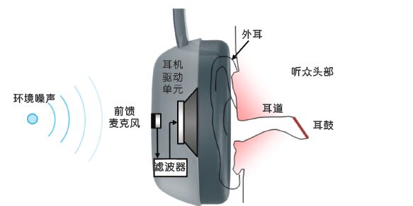
Figure 1: Feedforward noise canceling headphones
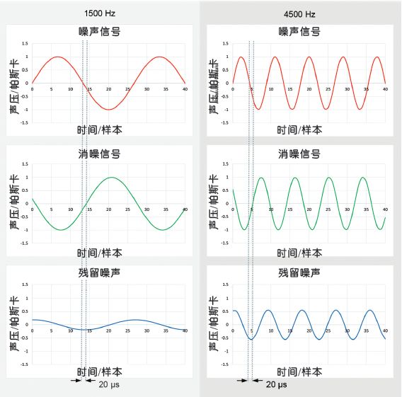
Figure 2: Effect of system delay at two different frequencies
The feedforward noise reduction bandwidth is limited to about 50 Hz by the headphone driver module at low frequencies and 3 kHz by the acoustic structure and signal processing delay at high frequencies. The delay can make it difficult to achieve a 180 degree phase reversal between the noise canceling signal and the noise signal, and the high frequency portion is more difficult to handle because of the shorter wavelength. Figure 2 shows the effect of 20μs delay on the noise reduction at two frequencies: at 1500Hz, the residual noise is about 1/5 (14dB ANC), but at 4500Hz, the residual noise is increased even if the delay is constant. To 3/5 (4dB ANC only).
Actually, the ambient noise can be detected as early as possible to compensate for the delay, which is convenient for the processor to process and output the noise canceling signal. In addition, placing the noise-reduction microphone at the entrance away from the ear canal is also beneficial to expand the angle of noise reduction (Fig. 3).
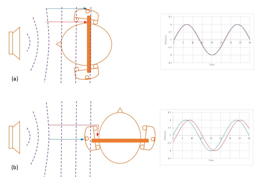
Figure 3: Directionality of feedforward noise reduction, (a) noise toward 0 degree (b) noise at 90 degrees
As shown in Figure 3, if the microphone is placed outside the earphone casing (ie away from the ear), when the angle between the microphone pickup hole and the noise is 0° and 90°, respectively, the time difference between the noise entering the microphone and the human ear is different, which means The noise reduction effect is directional. Controlling the path of ambient noise into the ear and placing a microphone close to the path solves this problem: Figure 4, an effective design is to open the open hole behind the speaker, the noise mainly from the leak hole, and the headphone drive unit into the person The ear can ensure that the time difference between the noise entering the microphone and the human ear at different angles is basically the same, thereby ensuring the consistency of the noise reduction effect.
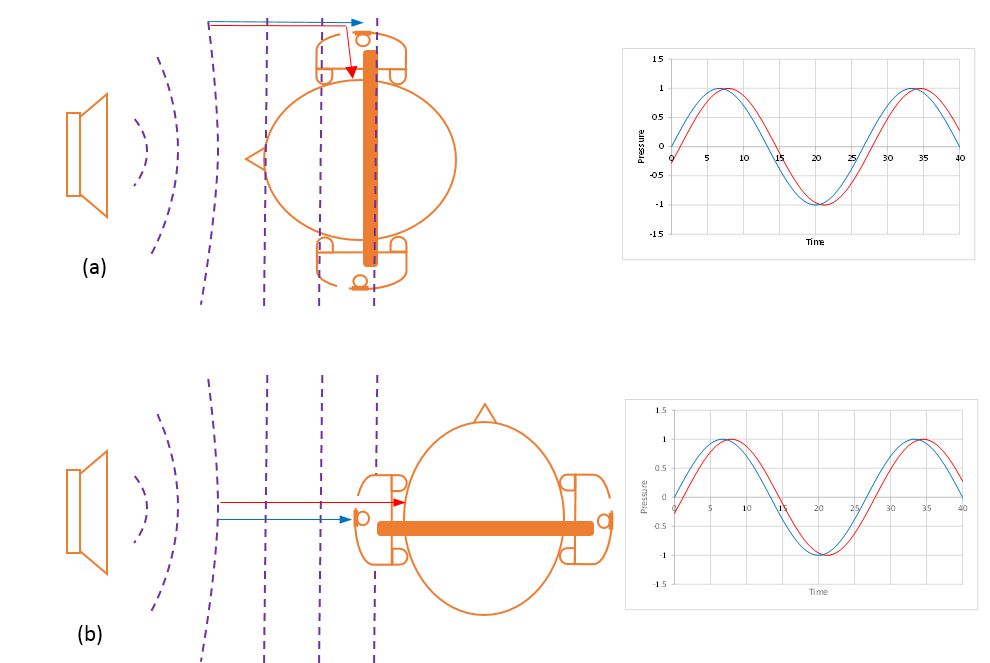
Figure 4: Place the microphone near the point where the noise enters the ear (a) Noise at 0 degree (b) Noise at 90 degrees
When the noise frequency is higher than 3 kHz, the wavelength of the sound is significantly shorter than that of the ear canal and the earphone cavity. Resonance may occur between the acoustic cavity and the speaker diaphragm, which makes it difficult to filter the design, and the noise reduction in the bandwidth is also limited by the system. Delay, so mainly rely on passive noise reduction. Passive noise reduction generally increases as the airtightness of the earphone increases, such as filling or reducing the size of the leak hole, but it also reduces the performance of the feedforward noise reduction at high frequencies. Therefore, trade-offs between passive noise reduction and active noise reduction in this frequency range need to be weighed.
Interestingly, consumers find it easier to evaluate ANC effects because they can be contrasted by quickly turning ANC on or off, but it is difficult to evaluate passive noise reduction because users will wear headphones in a short time. It is difficult to form a contrast by forgetting the level of environmental noise.
It can also be seen from Fig. 4 that the earphone is also designed to ensure the stability of the seal between the ear pad and the head so that the user can obtain stable acoustic characteristics and noise reduction performance.
In addition, it is recommended that the headphone speaker's frequency response and passive attenuation curve be smooth (for example, the Q value is not too high or too low) so that a simple digital filter can compensate the transfer function.
Feedback noise reduction
The feedback noise canceling headphone (Fig. 5) works by detecting the noise in the eardrum area and then forming a basic feedback loop to minimize the noise level in the area.
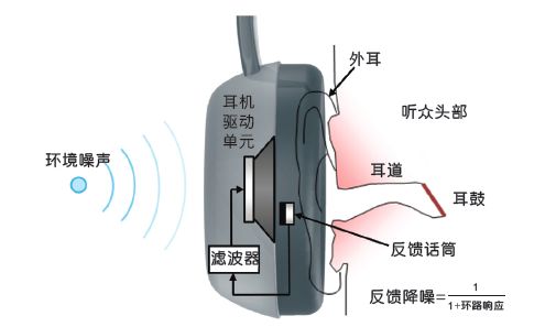
Figure 5: Feedback Noise Cancelling Headphones
Figure 5 is a formula for the design of a feedback noise reduction system. The entire "loop" is composed of the horn and the response of the microphone, as well as the filter. The formula shows that as the filter gain (and its loop gain) increases, the noise residue becomes smaller and the noise reduction performance is improved. However, if the phase of the loop is close to ±180°, the “loop†signal will be inverted and the “+†on the denominator will become “-â€. In this case, the loop gain size adjustment is limited because when it increases from 0.0 to 1.0, the result is amplification, and when it is equal to 1.0, the result is "divide by zero," which means instability and often The increase in frequency response causes whistling – it is important to avoid it.
In fact, the phase of the loop tends to be 180 degrees at a frequency of 10 Hz and tends to -180 degrees at a frequency of a few kHz. Therefore, the gain at these frequencies must be as large as possible but below 1.0. Usually the filter limits the bandwidth of the feedback noise reduction between 10 Hz and 1 kHz, and the noise reduction effect can also be derived from the filter.
The phase change in the high frequency portion of the loop is determined by factors such as system delay in the processor, speaker and speaker to microphone distance. Therefore, reducing any of these factors (using a light weight and high sensitivity speaker; placing the microphone close to the horn diaphragm; minimizing processor delay time) can increase the upper limit of the noise reduction bandwidth.
Since the feedback microphone is placed close to the speaker, the music played by the headphones is also mistaken for noise. As a result, the music signal from the horn is also noise-reduced, so it is also necessary to compensate by the circuit.
Digital signal processing
The building block of the environmental noise reduction digital system is as shown in Figure 6.
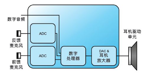
Figure 6: Basic block diagram of a digital noise reduction IC
There are several benefits to running an ANC filter in a digital processor:
Flexible – Capable of adapting filters for different environments, or sending ambient sound directly into headphones (similar to hearing aids), or digital interface communication with Bluetooth communication devices.
Faster development – ​​ANC filters are often designed to modify the peripheral filter circuit as acoustics are adjusted, and digital solutions can quickly adjust the filter circuitry inside the chip and immediately verify it.
The calibration process is optimized – because the tolerances of the acoustics affect the shape of the filter. Therefore, in production, there may be differences in the acoustic transfer function, which requires calibration of the headphones. The calibration process requires manual manual completion and takes a lot of time. Digital noise reduction technology can save the cost of this part of the resource.
Smaller in size - because there are fewer peripheral devices on the chip.
The disadvantages of digital ANC are as follows:
Higher power consumption
Digital systems have higher latency. Usually, the lower the delay, the better, the 20μs is a small percentage of the total loop delay.
It is difficult to distinguish the difference between an analog system with negligible delay and a digital system with a delay of less than 20 μs.
As wireless "ear-worn" devices become more popular, power consumption issues become critical. Therefore, any digital noise reduction solution must be energy efficient, especially in the ADC and DAC module sections. Keep the digital processor power to a minimum by running only the necessary programs (for example, using a simple filter and optimizing any other process) and reducing the clock frequency as much as possible. Speeding up the clock frequency can significantly reduce processor latency, but it also increases power consumption, so you need to weigh the relationship between the two.
Electronic noise
The electronic noise of the noise canceling headphones has a side effect on noise reduction. The main source of electronic noise is usually the microphone. Despite the recent popularity of silicon (MEMS), electret microphones (ECM) are still superior to MEMS in terms of signal-to-noise ratio. The industry-leading ECM microphone has a signal-to-noise ratio of 74 dB (test condition is 94dBSPL@1KHz), which means the noise floor is 20dBSPL. Although the bottom noise of the microphone is not high, it is still recommended to use a high SNR microphone as much as possible to avoid undesired noise in a quiet environment.
If the ANC is turned off while listening to music using a digital noise canceling headphone, the noise of the microphone will be shielded by the system, and the entire digital system must have low enough noise to ensure that the user enjoys pure music.
The SNR calculation method in a digital system generally takes the maximum undistorted output signal minus the discernable minimum output signal, and no noise is allowed to be heard in the system. The lower threshold of the human ear to hear the 1KHz frequency is defined as 0dBSPL, but you may find yourself less likely to be in a quieter environment than the 25dBSPL (the level of breathing is almost 1 meter heard by the human ear). Although recent standards (EN 50322 and IEC 600065:2014) stipulate that the maximum playback volume of a portable media player needs to be limited to 100 dBA, at some frequencies, the peak value of the signal that can be output by the earphone can reach approximately 125 dBSPL.
Therefore, the DAC specification needs to be defined to support at least 100dB signal-to-noise ratio (125dBSPL–25dBSPL) and to ensure that the digital domain signal-to-noise ratio is good enough. This is not difficult for the current digital processor, so the fixed-point algorithm is generally used instead of the high-power floating-point algorithm. In addition, the byte length is guaranteed to ensure that the quantization noise level is lower than that of the ADC and DAC. .
In addition, you need to choose a speaker with good sensitivity and low distortion. Distortion of the speaker can cause distortion of the generated noise canceling signal and reduce the level of noise reduction.
Overview of design points
Flexible digital noise reduction architecture design.
Minimize the acoustic delay of the entire system, using chips below 20μs delay to ensure noise reduction bandwidth.
A controllable path channel is built for the noise to enter the human ear to ensure the feedforward noise reduction effect.
The structure of the earphone is designed to meet the consistency of all users.
Choose a large-size leak hole design with passive noise reduction and a strong active noise reduction design, or choose a passive noise reduction small size leak hole design with a slightly weak active noise reduction design.
Adjust the chamber volume, leak hole and vent damping until smooth headphone and passive attenuation response are obtained.
Minimize the source of electronic noise, choose a high-SNR microphone, and ensure that the human ear can't hear the noise of the digital and DAC parts.
Remote Control Panel,Magnum Remote Panel,Remote Screen Panel,Magnum Energy Inverter Control Panel
SUZHOU DEVELPOWER ENERGY EQUIPMENT CO.,LTD , https://www.fisoph-power.com
