A new type of printable chipless RFID tag is proposed. The label is composed of a plurality of regular rectangular resonators etched on a rectangular dielectric plate. The tag structure has good stability for incident waves of various polarization directions. At the same time, a new chipless tag coding method is proposed. The code density of the tag is doubled without increasing the coupling between the resonators. The tag operates in the ultra-wideband frequency range of 3.1 to 10.6 GHz and has a code density of 3.3 bit/cm2 in a reasonable size of 22 mm x 11 mm. The radar cross section curve of the tag is given by simulation. The simulation result is consistent with the theoretical analysis, which verifies the rationality of the design. Compared with the traditional non-core labels, the label has the advantages of small size and high coding density. The label can be directly printed on ID cards or even papers using a single-layer conductor structure.
0 Preface
Radio frequency identification (RFID) systems are wireless data capture technologies that use readers to extract information from remotely placed tags. The system consists of two main components: a digitally encoded RFID tag and an RFID reader for extracting encoded data from the tag. For different occasions, you need to use a specific radio frequency identification system. Compared with traditional bar codes, RFID tags have the advantages of longer read range, penetration, and anti-fouling ability, so they have the potential to replace bar codes. However, current RFID tags have higher costs compared to bar codes, so they are still difficult to apply in the low cost field. The cost of widely used passive core RFID tags depends primarily on the silicon chips used internally [1]. Therefore, the current research focuses on the development of printable chipless RFID tags. If the cost of the tag can be reduced to 1 cent, there will be billions of tag demand in the low cost area.
At present, some chipless RFID tags are proposed in related literature. According to the chipless tag detection method, they are divided into time domain method, frequency domain method, and phase field method. Time-domain labeling is used to detect the tag ID based on a series of time-delayed pulse signals [3-5]. Labels based on the phase field method are proposed in [6] and consist of a number of patch antennas loaded by the nodes. A coreless tag constructed using folded dipole resonators is proposed in [7-8], but the tag is sensitive to polarization. In [9], a frequency-domain label with a maximum data capacity of 35 bits in the ultra-wideband (UWB) range from 3.1 GHz to 10.6 GHz is proposed. However, its size is large and it is difficult to be put into use. Compared to the time domain method and the phase field method, the coreless tag constructed based on the frequency domain method has a higher data density, and the coreless tag design and coding can be achieved by generating a formant at the determined frequency point. Therefore, they need a wider frequency range.
For most of the coreless labels proposed in the literature, the first issue to consider is the relationship between the size of the label and the coding capacity. The existing coreless labels constructed based on the frequency domain method use the frequency Domain OOK (On Off Keying) encoding [10-12]. The designed coreless tags all require a specific resonant unit to perform a specific one-bit encoding. This results in a linear relationship between the size of the tag and the number of bits of data. To obtain multi-bit encoded data, the tag size will also be With this increase, it also made it lost its commercial viability. The second issue to consider comes from the mutual coupling between the resonators. In order to overcome the problems faced in the above-mentioned coreless label design, a new type of printable coreless RFID tag is designed, and a new coreless label encoding method is proposed to enable the coreless label to reduce the resonator At the same time, a higher coding capacity can still be obtained while reducing the mutual coupling between resonators and increasing the printing tolerances.
1 Coreless tag structure and working principle
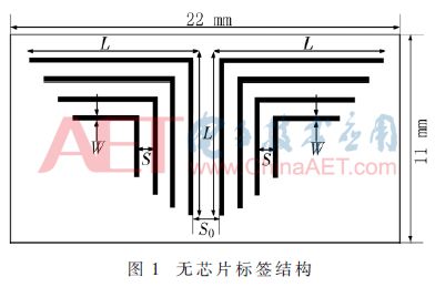
Figure 1 shows a coreless tag structure consisting of a plurality of right-angled resonators etched on a rectangular substrate. The substrate material was a PTFE copper foil F4BM. The relative permittivity εr of the substrate was 2.23, and the loss tangent tan δ was 0.000 7. Where L is the arm length of the right angle resonator, W is the arm width of the right angle resonator, S is the spacing between adjacent resonators, and S0 is the spacing between the two arrays.

Any metal structure that is exposed to radar waves can scatter incoming radar waves in a special way. The coreless tag is also a metal scatterer in nature, and when excited by radar waves, it can scatter backscattered signals associated with its own structure. The specific metal structure will produce radar cross section (RCS) curves with distinct peaks or troughs at specific frequency points. Each metal resonator corresponds to a resonant frequency point. When the metal resonator is present, the corresponding resonant frequency appears on the RCS spectrum of the echo signal. At this time, it is coded as '1'. When the metal resonator does not exist, its corresponding resonant frequency will not Produced, this time encoding is '0'. In this way, by changing the number of resonators, different encoding states of the tags can be obtained. This is also the more widely used label encoding method in the existing literature.
The working principle of the coreless RFID tag is shown in Figure 2. When the coreless tag is excited by the query signal transmitted from the reader, it will backscatter the echo signal related to its own structure, and the data will be encoded in this case. In the backscattering signal, after the reader receives the encoded backscatter signal through the receiving antenna, it will obtain the encoded information of the tag through a certain algorithm, thus completing the detection and identification of the coreless tag.

2 Characterization of Coreless Tags
2.1 Substrate Material Analysis
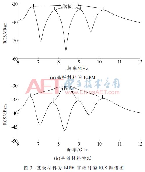
The tag structure is simulated and analyzed by 3D full-wave electromagnetic simulation software (FEKO). When the substrate material is F4BM, the coreless label RCS curve shown in Figure 3(a) is obtained. The structural parameters of the tag are as follows: The thickness of the substrate is 0.5 mm, size 22 mm x 11 mm, S 0.8 mm, S0 1.6 mm, arm width W 0.2 mm. From Fig. 3(a) we can find that the resonant frequency corresponding to the length L of the arm of the resonator is 6.68 GHz, 7.79 GHz, 9.01 GHz and 10.19 GHz, and the amplitude is close to -30 dBsm. The resonance characteristics are obvious and can be achieved. Clearly separate each resonant frequency point.
Keep the physical parameters of the above tag structure unchanged and change the material of the substrate. Using a paper with a relative dielectric constant of 2.25 and a loss tangent of 0.045 instead of the substrate, the RCS spectrum of the tag is shown in Figure 3(b). It is clearly seen that each resonant frequency is 6.67 GHz, 7.72 GHz, and 8.98 respectively. GHz and 10.18 GHz. Comparing Figure 3(a), it was found that when the material of the substrate was changed to paper, the resonant frequency was slightly reduced and the amplitude of the RCS spectrum was also reduced, and the amplitude was close to -35 dBsm. However, the resonance frequency can still be clearly identified, indicating that the paper material also has the ability to serve as a substrate material, which also provides experimental evidence for the printability of the coreless label (printed on paper or other documents).

2.2 Analysis of Polarization Angle of Incident Wave
In order to be able to adapt to a more complex detection environment, the stability of the incident wave of the tag to multiple polarization directions is verified here. Change the polarization direction of the incident wave, and let the polarization angle η be 0°, 30°, 60°, and 90°, respectively, and get the RCS spectrum diagram shown in FIG. 4 . Figure 4 shows that when the polarization direction of the incident wave is changed, the resonant frequency point will not be offset, and it can be concluded that this tag structure has the property of being insensitive to the polarization angle, that is, the structure has multiple polarizations. The incident wave in the direction maintains good stability. It can also be seen that as η gradually increases, |RCS| decreases. When the polarization angle is 90°, |RCS| is the smallest, which means that the intensity of the echo signal in a unit area is the largest. The intensity of the echo signal does not interfere with the detection of the tag, but it does affect the read range.

2.3 Resonator spacing analysis
When the metal resonator is exposed to radar waves, mutual coupling exists between adjacent resonators, which will have a certain impact on the resonance frequency. Keeping the above-mentioned physical parameters of the tag unchanged, the distance between adjacent resonators is changed to obtain the RCS curve of the tag, as shown in FIG. 5 .

It can be seen from the observation that the resonant frequency points corresponding to each resonator cannot be discerned in Figs. 5(a) and 5(b). Figure 5 (c) and Figure 5 (d) can clearly distinguish each resonance point, and with the increase of the spacing S, the resonance characteristics become more obvious, indicating that the appropriate increase in the spacing between adjacent resonators is conducive to The mutual coupling between the resonators is reduced so that a certain distance must be maintained between adjacent resonators.
3 frequency shift coding technology
3.1 coding ideas
From the above analysis, we can see that because there must be a certain distance between adjacent resonators without chip tags, the increase in the number of resonators will cause the size of the tag to increase. The existing coreless tags constructed based on the frequency domain method mostly use the OOK encoding method, and the use of the presence or absence of formants for encoding to obtain the encoding capacity of multiple bits requires an increase in the number of corresponding resonators, which is undoubtedly disadvantageous to the size of the tags. Miniaturization. In order to solve the above problems, the idea of ​​frequency shift technology is introduced into the design of the coreless tag, and a new tag encoding method is proposed here, which is referred to as frequency shift coding technology. Using this method, the coreless tag can double the code density of the tag without increasing the mutual coupling between the resonators.
The following describes the encoding process of the frequency shift coding technique using the label structure in FIG. 6 . The arm length L of a right angle resonator is inversely proportional to the resonant frequency, so by reducing or increasing the length L of the metal resonator, the resonant frequency becomes higher or lower, and in the RCS spectrogram it appears as a resonant The frequency points are shifted to the right (higher frequency) or left (lower frequency), and a variety of different coding states can be obtained by using the offset of the resonant frequency points. In order to easily represent the offset of the resonance frequency, four frequency shift parameters a, b, c, and d are defined, which are represented as the length of the shaded portion in FIG. 6 . Changes in the frequency shift parameters will cause the associated changes in the resonant frequency. For the tag structure in this paper, a single resonator can generate four different binary states, namely '01', '10', '11'. And '00' where '00' means the resonator is not present, ie no formant is generated.

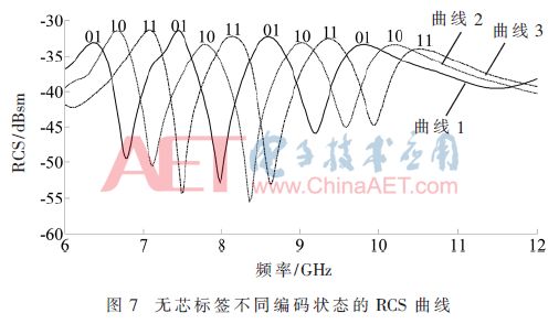
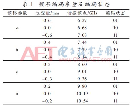
The coding state of the spectrogram is shown in Figure 7, and the relevant physical parameters under different coding states are given in Table 1. Observing Figure 7 clearly shows the position of the formant shift and the different code states resulting from the formant shift. This results in different tag IDs. The tag ID represented by curve 1 is '10 10 10 10'. The tag ID shown by 2 is '01 01 01 01', and the tag ID shown by curve 3 is '11 11 11 11'. Compared to the methods in the existing literature, the coreless label based on the frequency domain method increases the coding capacity by increasing the number of resonators. This not only increases the coding density, but also reduces the workload of label production.


3.2 Analysis of coding capacity
According to the above encoding method, each resonator has four different encoding states, namely '01', '10', '11', '00'. Therefore, each resonator here will actually encode 2 bits, and the 4 resonators in the text will encode 8 bits. However, if using OOK coding, each resonator has only two states, '0' and '1'. For the tag structure in the text, only 4 bit coding capacity can be obtained. Therefore, the coding capacity obtained by this coding method is twice that of the two-state coding technique proposed in [10-12].
In addition, if the reader has a higher resolution (smaller frequency shifts can be detected), the encoding capacity can be further increased in accordance with the idea of ​​frequency shift coding technology. The total coding capacity is calculated as follows:

Where N is the number of resonators in a single tag and 2M is the number of code states that each resonator can represent.
According to the given coding capacity calculation method, more coreless label structures can be designed in the future.
4 Conclusion
This paper designs a new type of printable chipless RFID tag. The tag consists of a plurality of regular rectangular resonators etched on a rectangular dielectric plate. Compared to the existing coreless tags, the tag has a small size, a high code density, and a significant resonance characteristic. Through the proposed frequency shift coding method of the coreless tag proposed in this paper, the code capacity of the tag is doubled without increasing the coupling between the resonators. The theoretical analysis and simulation results are consistent, and the reliability of the method is verified. . The chipless RFID tag designed is a single-layer conductor structure that can be directly pasted or printed on the ID card or paper, which is cheap, durable, stain-resistant and widely applicable.
UCOAX offer drone wire assembly solutions for many customers all over the world.
We have many solutions for machine vision data transmission and connection to solve the complex problem,worth of your contacting.
If you're interested in our drone link cable high speed low attenuation low noise with interface and length options, welcome to buy the quality products at competitive price with our factory. We also support customized production if you need. As one of the leading Custom Camera Link Cable manufacturers in China, we're waiting for your contact.
Drone Link Cable,D Line Cord Cover,D-Line Cable Cover,D Line Wire Cover
UCOAX , https://www.jsucoax.com
