PV inverters require a series of tests to verify their performance and immunity and to be certified before they are allowed to access the grid. When performing these test items, it is very important to have an AC/DC power supply that absorbs the energy of the inverter and can simulate the state of various power grids. AMETEK's MX or RS series of AC and DC power supplies is a superior test instrument with these features.
AMETEK's MX/RS series power supply can absorb up to 100% of the nominal power of the inverter backflow energy, which means that a RS90 power supply with a nominal power of 90KVA can absorb up to 90KW of the inverter output. Energy without additional load. This means that when the inverter is subjected to routine performance testing, the inverter can be directly connected to the MX/RS at the AC end, and the connection of the load is simplified, which simplifies the construction of the test platform.
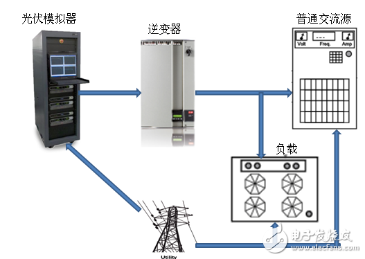
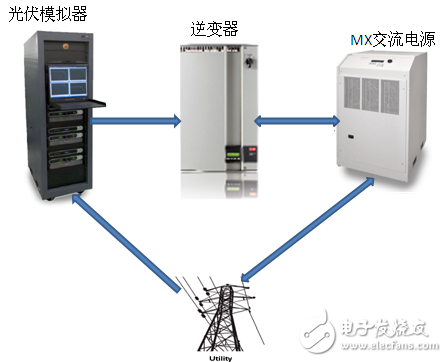
Figure 1 Test plan using a conventional power supply Figure 2 Test plan using MX
The traditional test platform needs to use the load to absorb the energy of the inverter. The load converts this part of energy into heat energy dissipation. When testing the high-power inverter, heat dissipation becomes a big problem. The corresponding laboratory must be able to Provide sufficient heat dissipation conditions, and to solve the heat dissipation problem, it will generate corresponding energy consumption. Simple calculation: Suppose you need to test the 100KW inverter, you need to provide 115KW of power to the DC to the DC PV simulator (the conversion efficiency of the PV simulator is 0.90, the efficiency of the inverter is 0.95). The 100KW energy generated by the transformer is dissipated by the load, and the heat dissipation requires an air conditioner energy consumption of 105KW (the air conditioner efficiency is 0.95), which means that the laboratory needs at least 220KW to test the 100KW inverter. The MX/RS series' unique regenerative mode allows up to 85% of the absorbed energy to be backflowed back to the grid, which greatly reduces energy losses.
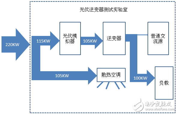
Figure 3 Laboratory energy consumption required to test a 100KW inverter using a conventional power supply (schematic diagram)
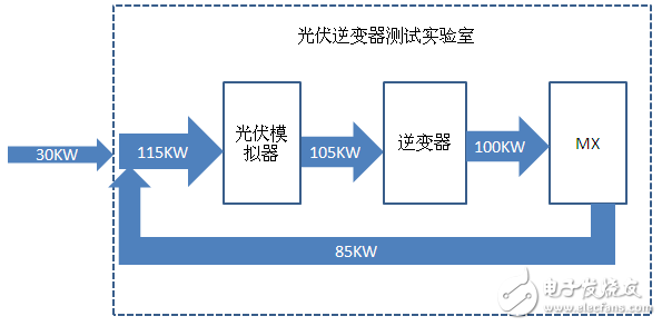
Figure 4 Laboratory energy consumption required to test a 100KW inverter using AMETEK MX/RS (schematic diagram)
Since MX/RS directly absorbs the backflow energy of the inverter, this enables the MX/RS to monitor the output power of the inverter in real time, so that the protection measures can be pre-defined for the abnormalities that may occur in the inverter, and the test system can be improved. Security. If the inverter to be tested is overloaded for a long time, it will cause damage to itself, and it may even damage the entire test equipment in the surrounding area. The pre-protection measures provided by MX/RS can be avoided by simple setting by the customer.
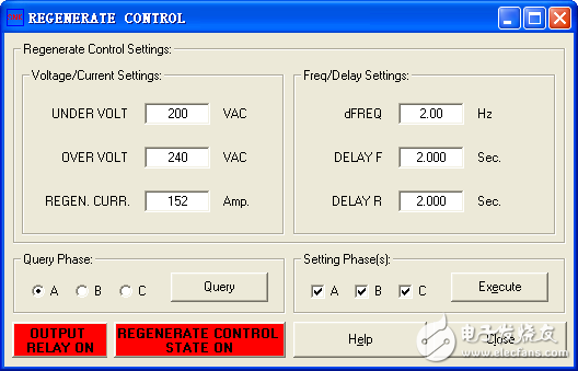
Figure 5 MX/RS settings for inverter protection
By setting the maximum current limit that allows the inverter to backfill the MX/RS (the value in the “REGEN CURR†column in Figure 5, different values ​​can be set for the A/B/C three-phase), the MX/RS will always monitor The input current, when a current exceeds this limit, the MX/RS will automatically raise the voltage so that the inverter reduces its output current and remains within the upper limit. Of course, the voltage rise must also be within a certain range. In general, we will limit it to 110% of the grid standard voltage (the value in the “OVER VOLT†column in Figure 5). If the MX/RS raises the voltage to 110% and the inverter's backflow current still exceeds the limit, the MX/RS is waiting for a few seconds (the value in the “Delay F†column in Figure 5). After that, the frequency of the circuit (the value in the "dFREQ" column in Figure 5) is directly changed to stop the inverter from going offline. Further, if the inverter still does not stop working after the grid frequency changes, the MX/RS will turn off the output after another wait time of several seconds (the value in the "DELAY R" column in Figure 5).
-----------------
This article is selected from the Electronic Consumers Network November "Test and Measurement Special" Change The World column, please indicate the source!

Terminals refer to Terminal Connectors,which are divided into single holes,double holes,sockets, hooks etc.From materials:copper plating, copper galvanizing, copper,aluminum,iron,etc.Their role is mainly to transmit electrical signals or to conduct electricity.
Our company's Terminal Connectors are divided into these series(as follow),which are hot-selling in recent few years:
Copper Tube Connectors(GTY)
JGK End Junction Terminal Connectors
JGA End Junction Terminal Connectors
JGY End Junction Terminal Connectors
JGB End Junction Terminal Connectors
DTL-1 Aluminium-Copper Terminal Connector
DTL-2 Aluminium-Copper Terminal Connector
DT Copper End Junction Terminals
DL Aluminium End Junction Terminals
Bus-Bar Terminal Connector
SM Insulate Terminal Connectors
One hole long barrel copper lugs
Two holes long barrel copper lugs
Terminal Connector
Terminal Connectors,Sc Cable Lug,Cable Lug,Terminal Lug
Ningbo Bond Industrial Electric Co., Ltd. , https://www.bondelectro.com
