In the submillimeter wave band, compared to the microwave millimeter wave band, the corresponding device size is smaller due to higher frequency and shorter wavelength. The antenna is closely related to the size and wavelength, and the design of the sub-millimeter wave band is very challenging. On the one hand, using new materials and new processes to process antennas with small dimensions and submillimeter tolerance requirements; on the other hand, according to the characteristics of submillimeter wave systems, we will study planar integrated antennas, antennas, detectors, mixers, etc. The devices are integrated using integrated process technology to avoid connection problems caused by discrete structures.
MEMS technology was gradually formed in the 1990s, with many advantages such as high performance, high efficiency, low cost, and high reliability. MEMS technology has been widely used in microwave and millimeter wave. Because of its special superiority to mesoscale (1μm ~ 1mm) model processing, it has obvious advantages in the manufacture of tiny devices used in the THz band.
For planar integrated antennas in the sub-millimeter wave band, substrate media is an important factor to consider. A planar antenna on a substrate medium tends to radiate most of the energy into the medium rather than the free space on the other side. There are usually two ways to solve this problem. One is to integrate a lens with the same dielectric constant on one side of the substrate medium; the other is to use a very thin substrate medium. The former method requires a high lens processing process, absorption and reflection losses in the dielectric lens are unavoidable, and the 1/4 λ matching layer technique needs to be improved. The latter method reduces the influence of the substrate medium, and the antenna can be approximated in free space, but the support of the thin substrate is weak and needs to be structurally improved.
In 1990, Rebeiz et al. designed an integrated horn antenna. They processed the planar antenna on a dielectric diaphragm of the order of μm thick. The diaphragm was built into a silicon pyramid horn cavity that was etched by MEMS. This method solves the problem of supporting the film well and enhances the radiation of the antenna. However, due to the limitation of the thickness of the silicon wafer (usually not exceeding 800 μm), the caliber of the integrated horn is strictly limited. In order to enhance the radiation, they will machine the horn. The port and integrated horn antenna are combined to form a "quasi-integrated" horn antenna to enhance the radiation characteristics. The “quasi-integration†scheme is feasible in the sub-millimeter wave frequency band with low frequency, and it is very difficult to machine machining at around 900 GHz.
This paper proposes a new horn structure based on MEMS technology, designed for integrated antennas in the sub-millimeter wave high frequency band.
2 process
The main material of the MEMS process used in this paper is monocrystalline silicon, which has a special crystal plane structure. The MEMS processing used is dry etching, namely deep reac TI etching (DRIE) and wet KOH etching. In both processes, single crystal Si is important. The material, which has many good characteristics, significantly changes the properties of the semiconductor with a small amount of dopants, can obtain nanometer surface roughness by mechanochemical polishing, good elasticity and rigidity coefficient, and anisotropic etching and cleavage, etc. Good characteristics. Under the wet etching of Si, the V-groove can be fabricated on the (100) substrate, and the (100) plane forms a 54.7° angle with the (111) plane. The vertical side grooves can be fabricated on the (110) substrate. Its dimensional tolerance can reach 1.0μm.
Dry etching can process complex shapes of graphics, but the depth of the same version is the same, and not too deep, making it impossible to make more complex structures in the longitudinal direction. Wet etching can etch a specific angle structure longitudinally using the lattice direction of single crystal silicon, but requires a simple mask shape.
3 structure
The integrated horn antenna fabrication process designed by Rebeiz et al. uses only the wet etching process. Due to the characteristics of the silicon crystal, the apex angle of the prism back cavity is 70.6 ̊, and the height of the front cavity is limited by the thickness of the silicon wafer. It can be superimposed by a multilayer wafer to increase its height, but the horn angle is limited to 70.6 ̊, so the radiation performance of the antenna is relatively fixed, especially the radiation pattern of the antenna. Although it can be improved by integrating mechanically machined horn structures with different opening angles before the front cavity, in the 900 GHz band, the wavelength is only more than 300 μm, and the machining accuracy is difficult to guarantee.
To this end, this paper proposes a new integrated horn antenna structure fabricated entirely using MEMS technology, as shown in the figure.

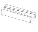
Figure 1 Schematic diagram of the new integrated horn antenna structure
Part A is a pyramidal horn cavity machined on a silicon wafer by a wet etching process. The angle of the apex angle is 70.6 ÌŠ, and a gold layer is sputtered inside the cavity to metallize it. Part B is a dipole antenna fabricated on a film by photolithography, and part C is an octagonal speaker structure fabricated by a combination of dry etching and wet etching. The processing steps are as follows:
Step 1: Dry etching, etching depth t_dry, horn opening angle θ. In order to integrate with the pyramid horn back cavity structure, t_dry is 1/2 of the back cavity opening width a.
Step 2: KOH wet etching, corrosion depth t_wet, forming a longitudinal angle ε. At the end of this step, half of the octagonal horn is formed.
Step 3: Sputter a gold layer on the inside of the horn to metallize it. Then, the two identical wafers are bonded together, and the excess portion is removed by the dicing technique to expose the speaker opening to form the C portion of the integrated horn, that is, the octagonal horn front cavity.
Finally, the A-section pyramid horn back cavity, the B-part film substrate plane antenna and the C-part horn front cavity are integrated to form the final integrated horn structure. The groove can be etched on the pyramid cavity A, which is reserved for the transmission line and circuit structure integrated with the planar antenna.
The above structure completely utilizes the MEMS process, which greatly satisfies the requirement of processing precision, and the structure can change the opening angle θ of the front cavity portion and the wet etching depth t_wet. The dry etch depth t_dry is equal to half the height of the pyramid horn back cavity. Select the appropriate parameters according to different application requirements to obtain a reasonable direction.
4 simulation
The finite element method is used to model the overall structure of the integrated speaker. In the model, the planar integrated antenna selects the dipole antenna structure, the dipole length is 0.4λ, the operating frequency is 900GHz, and its radiation pattern and standing wave characteristics are as follows:
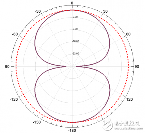
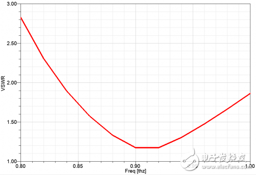
Fig. 2 Radiation pattern and standing wave curve of 900GHz dipole antenna
The height of the pyramid horn cavity A has a great influence on the performance of the integrated horn antenna. After the parameters θ and t_wet of the fixed B part, the heights of the horn cavity are selected to be 0.4λ, 0.7λ and 0.9λ, respectively. :
When ha increases, the width of the main lobe of the antenna increases, and after reaching 0.8λ, significant cracks appear.
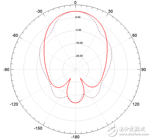
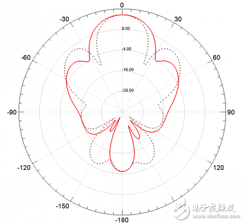
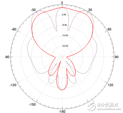
Figure 3 Radiation pattern at different back cavity heights (0.4λ, 0.7λ and 0.9λ)
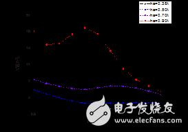
Figure 4 VSWR at different back cavity heights (0.4λ, 0.5λ, 0.7λ, and 0.9λ)
It can be seen from the results of the standing wave curve that as the ha increases, the standing wave appears to deteriorate. Therefore, the radiation characteristics and standing wave characteristics of the integrated antenna are selected, ha = 0.4λ. The height ha of the horn back cavity has a significant influence on the radiation characteristics and matching characteristics of the antenna, and its structure is similar to the angle reflector.
Select ha=0.4λ, l=1.4mm, set different dry etching opening angle θ values, and select the appropriate wet etching depth t_wet, so that the shape of the bell diameter is rotationally symmetrical. When the value of θ is selected from 20 ̊, 30 ̊ and 40 分别, the radiation pattern and results are obtained as follows:
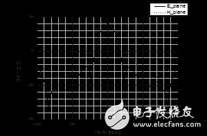
Figure 5 dry etching angle θ = 30 ̊
Table 1 Results of different dry etching angles θ
θ (degrees) gain HPBW (E face) HPBW (H face)
20 ÌŠ14.140 ÌŠ34 ÌŠ
30 ÌŠ15.928 ÌŠ28 ÌŠ
40 ÌŠ 17.224 ÌŠ 26 ÌŠ
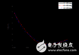
Figure 6 Under different horn angles (θ=20 ̊, θ=40 ̊, θ=60 ̊)
Antenna standing wave graph
It can be seen from the above pattern and results that the change of the opening angle of the dry etching horn affects the radiation pattern of the antenna. When the horn angle θ is increased, the 3dB lobe width of the antenna is narrowed and the gain is increased. This is because under the condition of fixing the horn length, the larger the opening angle θ, the larger the horn diameter, and thus the lobes are narrower and The gain is greater. This is consistent with the traditional horn antenna theory. The standing wave curve of the antenna does not change greatly with the change of the horn angle, which indicates that the main factor affecting the antenna matching is the height of the back cavity. In practical applications, an integrated horn antenna that meets the application requirements can be designed by controlling the opening angle θ of the horn opening. In the simulation, we choose the wet etching depth t_wet so that the height and width of the horn diameter are basically the same. In practical applications, the choice of t_wet should be selected according to the requirements of the E-face pattern. The limit case is that no wet etching is performed. Only dry etching is performed. The depth t_wet of the wet etching is limited by the thickness of the silicon wafer.
In the above three different θ angle directions, when θ=30 ̊, the E-plane and H-plane main lobes are substantially symmetrical, and the θ value is fixed, and the octagonal horn front cavity length l is changed.
Table 2 Results of different front cavity length l
l (mm) gain HPBW (E surface) HPBW (H surface)
1.415.928 ÌŠ28 ÌŠ
2 ÌŠ18.622 ÌŠ22 ÌŠ
2.5 ÌŠ2018 ÌŠ18 ÌŠ
It can be seen from the results that when the value of θ is fixed and the value of l is changed, although the length of the antenna changes, the main lobe widths of the E-plane and H-plane patterns remain substantially the same. As the value of l increases, the antenna gain increases and the main lobe becomes narrower.
5 Conclusion
Through the above finite element analysis of the integrated horn antenna in the 900 GHz band, it can be seen that our proposed octal-shaped front cavity integrated horn antenna based on MEMS technology can improve the radiation characteristics of the planar integrated antenna. The controllable parameters of the horn antenna include the back cavity height ha, the horn front cavity opening angle θ, the horn front cavity length l, the horn front cavity dry etching depth t_dry, and the horn front cavity wet etching depth t_wet, by comprehensively optimizing these parameters, We can design an integrated horn antenna that fits the design application. The form of the planar integrated antenna is not limited to the use of a dipole antenna, and other types of planar integrated antennas can be used to achieve proper bandwidth, polarization, and the like. In further research, an integrated horn antenna can be assembled into an array.
Canaan is a leading provider of supercomputing solutions, distinguished for superior cost-efficiencies and performance. In addressing the limitations of today`s computing hardware, Canaan strives to advance the world we live in by powering transformative technologies.
Canaan is renowned for having invented the world`s first ASIC-powered Bitcoin Mining Machine in 2013, radically catalysing the growth of a computationally-advanced bitcoin mining sector.
Developed through academic research, rigorous expertise in semiconductor design, and backed by a robust network of strategic partners, Canaan continues to expand its suite of advanced hardware offerings, exploring opportunities across some of the world`s most exciting emerging technologies.
Canaan AvalonMiner:Canaan AvalonMiner 821,Canaan AvalonMiner 841,Canaan AvalonMiner 741,Canaan AvalonMiner 1246,Canaan AvalonMiner 921,Canaan AvalonMiner 1166 Pro
Canaan Avalonminer,1166 Pro 66T,Avalon 821,Avalon 1246,avalon miner
Shenzhen YLHM Technology Co., Ltd. , https://www.ylhm-tech.com
