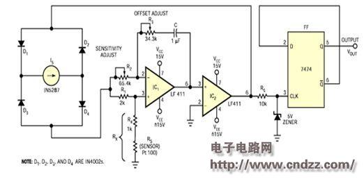
Resistance-based sensors, such as stress gauges and piezoresistive devices, are commonly used to measure a variety of physical parameters. For devices that use digital processors or microcontrollers for data acquisition and signal processing, the response of the sensor must be in a form suitable for conversion to a digital format. It is advisable to convert the resistance change of such a sensor into a proportional frequency or time interval, so you can easily obtain a digital output signal with a counter or timer. The circuit shown in Figure 1 linearly converts the resistance RS of the sensor into a time interval proportional to it. This circuit is actually a relaxation oscillator consisting of a current source, a bridge amplifier, a comparator and a flip-flop. The current IS is split into two paths, passing through R1 and R2, respectively, as if the two resistors were connected in parallel. Assuming the op amp is an ideal amplifier, the circuit acts as an oscillator when RX (R4+RS) is greater than R1R3/R2.
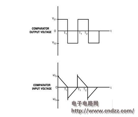
This circuit produces a variety of waveforms at the input and output of comparator IC2 (Figure 2). T1 and T2 are the time intervals when the output levels of the comparators are VS1 and -VS2, respectively. The output voltage of IC2 can be used as the clock input for the D flip-flop if its level can be changed by a Zener diode circuit. You can get alternating high- and low-level square wave outputs from the 7474 trigger for a time period of T=4C(R2RX-R1R3)/R1. This formula shows that the circuit converts the resistance change of the sensor into a time interval ΔT proportional to it, and the conversion sensitivity is ΔT / ΔRS = 4C (R2 / R1). The circuit shown in Figure 1 achieves the following outstanding performance:
â— The sensor is grounded. You can easily change the conversion sensitivity by changing R1 or R2.
â— You can change the offset value TO (related to the change in the resistance caused by the change in the resistance of the sensor) by changing R3 or R4 without affecting the conversion sensitivity.
â— The offset voltage of the op amp changes T1 and T2 in the opposite way, so the total effect on T(T1+T2) is small.
â— Due to the presence of the current source, the output is largely insensitive to the noise voltage of the current source line and the changes in VS1 and VS2.
Consider an example where a resistance range of 119.4 Ω to 138.51 Ω for a Pt-100 (platinum RTD) sensor is converted to a time period of 10 to 12.5 ms. The temperature range corresponding to the resistance range of 119.4 Ω to 138.51 Ω is 50 ° C to 100 ° C. This design is simple. Since the current flowing through the sensor is part of the IS, the IS should be small enough to bring the self-heating error to an acceptable low level. An IN5287 current regulator is used in this design, which provides an IS and dynamic impedance of approximately 0.33 mA and better than 1.35 MΩ, respectively. If the current source performs well, you can use a circuit based on the regulator IC. The next step is to adjust the resistance of R2 until a suitable and feasible value is chosen for R1 and C until the required sensitivity is obtained: 130.82 μS/Ω. Thereafter, R3 is adjusted to obtain the offset required for the output (T) with R4 fixed. Figure 1 shows the parameter values ​​for the components used in this example. The tolerance of the resistor is 1%, the rated power is 0.25W, and C is a polycarbonate capacitor. 
Figure 1. This simple circuit converts the resistance reading into a time period output. 
Figure 2 These waveforms represent the inputs and outputs of comparator IC2.
Dynamic Harmonic Filtering Compensation Device
Harmonic power quality suppression cabinet is a new type of power electronic device for dynamic harmonic filtering. It can filter out 51 harmonics, and the maximum capacity of a single cabinet can reach 600A. Through advanced algorithms and high-performance core electronic components, the shortcomings of conventional harmonic filters and reactive power compensation are overcome, and the harmonic filtering and reactive power compensation functions are systematically realized.
Dynamic Harmonic Filtering Compensation Device,Pfc Hybird Compensation Cabinet,Compensation Active Harmonic Filter,Dynamic Filter Compensation Device
Jiangsu Sfere Electric Co., Ltd , https://www.elecnova-global.com
