The purpose of the setting: Why is it set? When do you need to set up?
Essentially, the job of the servo system is to reduce the error of the command input and output to zero. The "strength" of trying to reduce the error to zero depends on how the system is set. Simply put, tuning is to adjust the response of the servo system to any given error to give the system a given response. In most high-performance servo applications, the goal is to achieve a high response rate (also known as bandwidth) for errors and to keep errors as small as possible during operation and stall. Of course, many applications require a slower response rate; there is always a certain tracking error in system motion. A well-tuned system does not have to eliminate the error as quickly as possible, but rather to react to the error that the machine designer expects.
Generally speaking, before the servo system is installed on the machine, it should be tested and confirmed that the system is running smoothly. If the system is running rough before loading and loading, there is little chance of achieving target performance after installation. The following figure shows the tuning process and clues of the SureServo servo system:

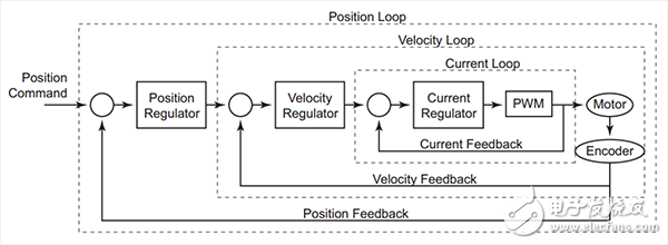
The control loop flow chart illustrates the basic principle of the servo controller driving the load. As shown in the figure, the servo control system is mainly composed of three parts:
Current loop, speed loop, position loop
For servo motor users, only the speed loop and position loop parameters need to be set. In addition to selecting the motor power model, the current loop does not require any user interaction and is set to a fixed bandwidth of 1.8KHz. If the motor power model is selected incorrectly, the performance of the current loop will be affected and the motor may eventually be damaged. The output of the speed loop is connected to the current loop. The operating bandwidth of the speed loop can be adjusted up to 450 Hz. The output of the position loop is connected to the speed loop and its bandwidth can be adjusted up to 300 Hz.
As you can see, the current loop is the fastest response, with the goal of quickly processing and tracking the output to the speed loop. Even when the speed loop is set to the highest operating bandwidth, the current loop is still four times faster than this, in order to ensure system stability. Again, the speed loop should always respond faster than the position loop. Otherwise, if the position loop updates its target to the speed loop faster than the speed loop correction error, the system may only become unstable. (the system has no choice but to become unstable)
Control law
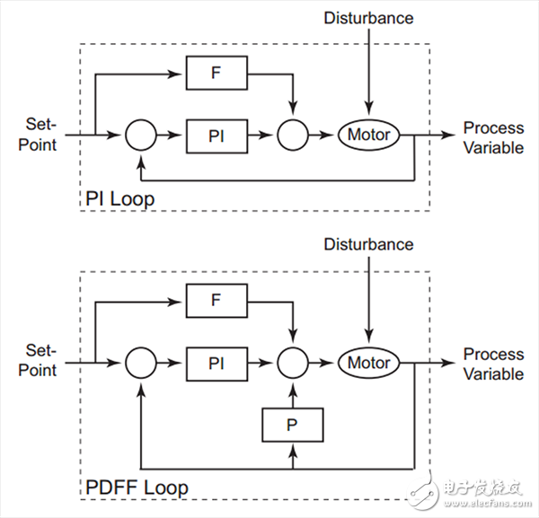
There are two options you can choose from:
- PI (ProporTIonal-Integral) Proportional-Integral
- PDFF (Pseudo-DerivaTIve Feedback and Feedforward) Pseudo-differential feedback feedforward
The block diagram is as follows:

Available tuning mode
Define the inertia rate = load moment of inertia / motor moment of inertia, generally about 10
Enter the parameters manually.
Simple mode. Suitable for a wide range of load changes. The target stiffness and inertia rate are input by the user, and the system automatically sets a conservative value for the adaptive self-tuning mode. The system automatically adjusts parameters dynamically during operation based on varying load inertia.
Fixed auto tuning mode. When the load inertia is known, the target stiffness and inertia law are input by the user, and the system automatically adjusts the parameters. The load variation range cannot be too large.
M12 Connector,M12 Male Plug Connector,M12 Aviation Plug Connector,M12 Female Connector
Changzhou Kingsun New Energy Technology Co., Ltd. , https://www.aioconn.com
