When winter vacation and teammates did together, it would be a bit cold in winter in Wuhan. My teacher is responsible for guiding us. Others are very good, treat students with affectionate homes, every time we encounter problems he can always answer our place where problems need to be debugged or modified parameters, even if we look at it too slowly He took the initiative to use a soldering iron to modify the board parameter. In my student life, such teachers are rarely seen. Most mentors will only ask you to do what you read and not to teach yourself or even do it yourself. So I was drunk when I met such mentors. Then the winter vacations were very conscious and they took the initiative to stay with him. It wasn't like the boss was forced to stay in school for some years to come. Therefore, choosing a teacher is like selecting an object and choosing the wrong one is not happy.
To say that it is a receiver, in fact, the main workload is focused on the local oscillator because the filter after mixing allows only one signal to pass. This means that when the local oscillator is fixed, the incoming signal is fixed. After the signal received by the receiver passes through the pre-selected frequency, it enters the mixing end. The mixing local oscillator is the key to the selection signal. When the mixing local oscillator is changed, an incoming frequency will be selected. This is the reception. The main thing in the signal.
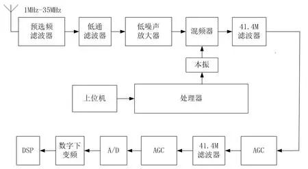
A signal comes in first through a preselected frequency and then through a low noise emission. The opa here is critical because the incoming signal sensitivity is so low that an amplifier cannot be chosen at random. Because at the previous level his noise figure is higher. Before the image suppression, my blog explained that after involving many indicators, there is an opportunity to summarize them. The incoming signal of the antenna enters the mixer with the local oscillator and passes through the 41.4M crystal filter. Because the output selects the presence of the crystal filter, that is, when the local oscillator is fixed, the frequency of the selected antenna is fixed. This is the main theory of the receiver. The DDS here is very critical, because it is almost the core of the entire system, and the frequency of selection is determined by it. The DDS we use is the AD9953, which requires a high clock and is compatible with the local oscillator made by the phase-locked loop. After entering the mixing signal, the signal is passed through a filter and automatic gain control is performed. The reason for using two-stage signal automatic gain and filtering is to better filter out the waveform. Then enter the analog-to-digital conversion AD for digital acquisition, and then convert the frequency of the signal to the baseband signal after down-conversion and send it to the DSP for processing.
Indicator requirements:
Frequency range: 1-35M
Frequency interval: 1Hz
Reference sensitivity: port voltage ≤ 0.5uV IF suppression and image rejection >90db larger signal to noise ratio >40db
Blocking: ≥100dBuV
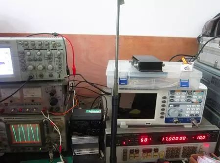
Let's take a look at the usual instruments. This picture can almost represent the usual life status and contact.
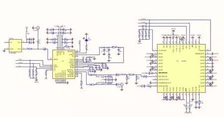
Look at the schematic. This is part of the local oscillator.
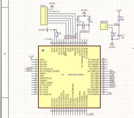
The ti of the processor.
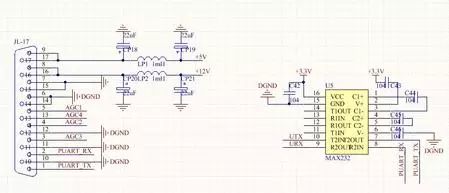
Although the USB chip is popular on the market, my teacher has a special feeling for 232. Every time he says that he should use this, he can save money.
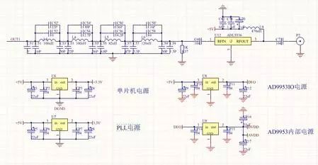
A multi-stage filter is used in the middle and a fixed gain amplifier is added afterwards. Below are multiple power sections.
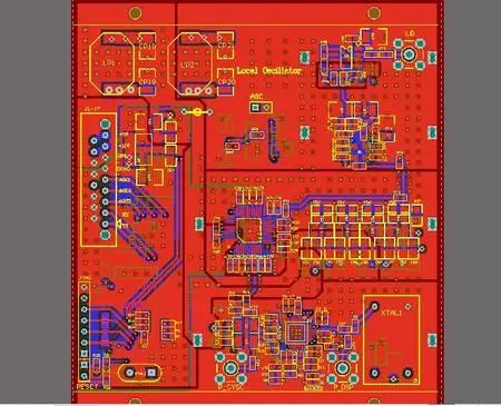
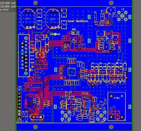
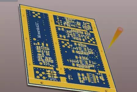
The local oscillator part of the PCB and 3D drawings.
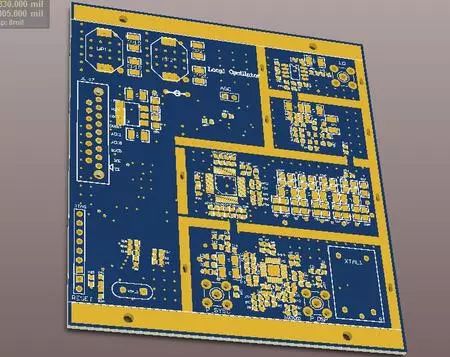
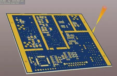
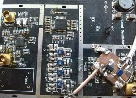
Physical board sub-map,
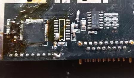
This is MSP430
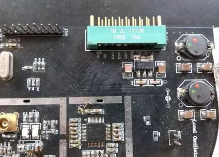
Dds is here.
After the signal is mixed and filtered, the AGC is used to stabilize the amplitude of the signal and send it to the post-processing. The chip used ADI's AD8367 and AD603. Multi-level 603. The previous experiment used AD605, but 605 was turned off by me. After the change of the program used this. My teacher especially likes the AD8367, not only because of its high bandwidth! There are many options for AGC. The reason for adopting 603 is not only because of his familiarity, but also because of his high portability. In a typical solution of ADI, it matches the automatic gain of AD8367.
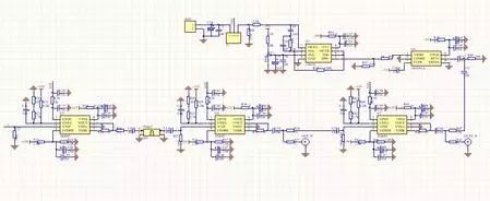
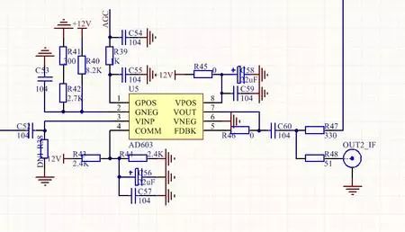
Enlarged view.
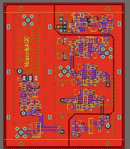
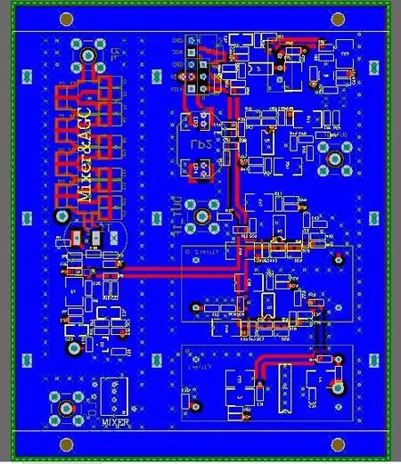
The AGC is designed here and the AD8367 is used to detect waves. 603 is responsible for program control.
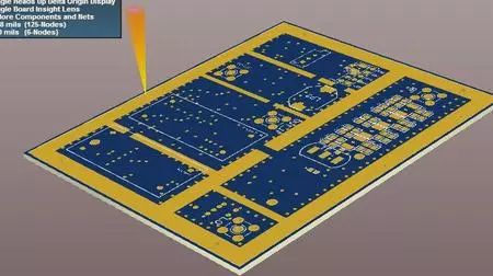
The final indicator tests the spectrum of the crystal oscillator source.
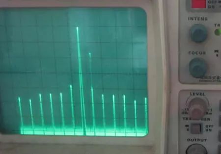
Single signal spectrum
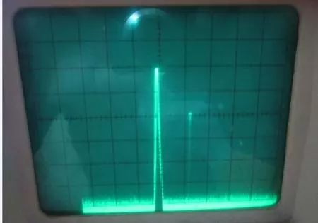
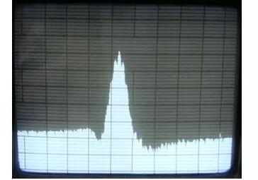
The details of the test are not explained in more detail. The indicators tested include bandwidth, sensitivity, blocking, and image rejection. Most of the indicators met the standard. Previous receiver diagram.
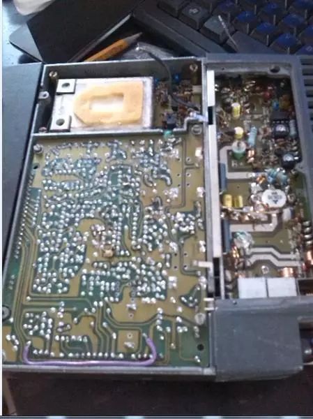
With part of the AD9953 program.
Main program part: void main( void ){ /* The following six lines close all IO ports */
P1DIR = 0XFF; P1OUT = 0XFF;
P2DIR = 0XFF; P2OUT = 0XFF;
P3DIR = 0XFF; P3OUT = 0XFF;
P4DIR = 0XFF; P4OUT = 0XFF;
P5DIR = 0XFF; P5OUT = 0XFF;
P6DIR = 0XFF; P6OUT = 0XFF;
WDTCTL = WDTPW + WDTHOLD;
// Close watchdog
InitAD9953();
// Initialize // InitDAC12();
// Initialize DA InitUART0();
// Initialize the serial port
InitADF4350(); /
/ Initialize the PLL
AD9953_WriteFreq(30000000);
While(1)
{
UART0_ChangeFreq();//
UART0_ChangeDA();//
a=10000;//
If(flag==3)//
{//
a=10000;//
While(a--);//
i=i+100000;//
If(i>75000000) i=46500000;//
AD9953_WriteFreq(i); //
}
//
DA_Sweep=DA_Sweep+10;//
If(DA_Sweep>3000) i=0;//
DAC12_0DAT=DA_Sweep;
}}
DDS is mainly used in the AD99 series. The program refers to the code example of ADI's official website, you can download it if you want to refer to it. It would be nice to modify it on that basis. In addition, only the program part of the PLL can be downloaded, and the reference can be downloaded. The remaining MCU modules have only a serial program, which is similar to the combination.
DDS program part:
Void WriteByte(unsigned char data){ PORT_SCLK_OUT; PORT_SDIO_OUT;
Unsigned char i;
Unsigned char temp; temp = data; for(i=0;i<8;i++)
//feed 1 byte of data {CLR_SCLK; nNop(4);
If(temp&0x80)
SET_SDIO;
Else
CLR_SDIO;
Temp<<=1;
nNop(2);
SET_SCLK;
nNop(4);
}
}
PS: The debugging of this project took a lot of time. The preliminary design was mainly discussed with several classmates and my teacher. Another major part is the amplification part, which is not implemented by ordinary amplifiers, but is generated by tuning amplification. There is no detailed explanation here. Later went to other places to test it. It took nearly half a year. Used to commemorate the next. In fact, as long as each project is carefully explored and debugged, you can learn a lot in it, even if it is a very detailed thing can be described very clearly. So if you ask someone else to participate, you can almost ask them. This project involves many indicators. Interested ones can refer to the national standard.
The utility model discloses an Electronic Cigarette with atomizer oil core separation structure, which comprises a atomizer assembly and a battery assembly; The utility model has the advantages of reasonable structure design and high practicability. During operation, because the oil storage tank of the atomizer is completely sealed and the oil guide material is completely isolated from the oil guide material, the oil guide material will never contact with the oil guide material in the storage process
Advantages:
Oil core separation, Mesh removable heating core, Ultra quiet design,100% oil leakage free, Excellent taste, Cost far less than the industry price.
A variety of colors and finishing are available, can be adjusted according to your market needs.
Oil Coil Separation Pod Patent,Oil Coil Separetion Vape Pod Oem,Innovated Vape Products Oem,Oil Coil Separation Vape Products Oem
Shenzhen MASON VAP Technology Co., Ltd. , https://www.disposablevapepenfactory.com
