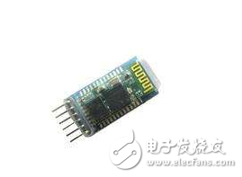
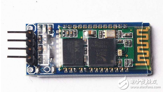
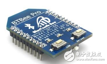
Bluetooth HC05 is a master-slave Bluetooth serial port module. Simply put, when the Bluetooth device is successfully paired with the Bluetooth device, we can ignore the communication protocol inside Bluetooth and directly use Bluetooth as the serial port. When a connection is established, two devices use one channel in common, that is, the same serial port, one device sends data to the channel, and the other device can receive data in the channel.
How to use hc05 Bluetooth module----hc05 Bluetooth module to set AT commandThere are three types of general Bluetooth modules used.
First: Bluetooth slave device and computer pairing connection (1, the computer comes with Bluetooth 2, the computer does not have Bluetooth, this requires a Bluetooth adapter)
Second: Bluetooth slave device and mobile phone paired connection
Third: Bluetooth slave device is paired with Bluetooth master device

There are roughly three ways to set the AT mode of the HC05 Bluetooth module:
First, the default settings
Second, use USB to UART module settings
Third, set up with the serial port program of the main controller with Bluetooth settings
First: the main default settings:
Module job role: slave mode
Serial port parameters: 38400bits/s stop bit 1 bit without parity
Pairing code: 1234
Equipment Name: HC-05
Connection mode: any Bluetooth device connection mode
Second: set up Bluetooth with USBtoUART module
Bluetooth HC05 module exploration - set AT command
Bluetooth and USB to serial port module connection, RXD-TXTXD-RXVCC-VCCGND-GND
To set the Bluetooth AT command, the AT pin must be set high, then the Bluetooth module is connected. When the Bluetooth module status light changes to slow flash, it indicates that the AT mode has been entered. (j Insert the Bluetooth module and the serial port module, and connect the corresponding pin of the AT to the VCC with a jumper.) At this time, connect the serial port module to the computer, and open the HyperTerminal or the serial port debugging assistant to start setting the AT mode.
1, set the AT mode baud rate is 38400
1. [AT mode] PIO11 of two Bluetooth modules is connected to VCC. After power-on, it enters AT command mode, and all use USB to TTL module to connect to the computer's USB interface.
2. [Open Serial Port Debugging Assistant] Open two serial port debugging windows, one to open the COM port of Bluetooth A, and one to open the COM port of Bluetooth B. [The default baud rate is generally 38400]
3, [Restore A default setting] Serial debugging assistant A, restore Bluetooth A default settings: AT+ORGL [ie enter, line feed, enter a carriage return on the serial debugging assistant]

4, [Set A pairing code] Serial debugging assistant A, configure the pairing code of Bluetooth A: AT+PSWD=1212 [Bluetooth A and Bluetooth B have the same pairing code, so that they can be successfully paired]
5, [Set A main mode] Serial debugging assistant A, configure Bluetooth A as host mode: AT+ROLE=1
6, [Restore B default settings] Serial debugging assistant B, restore Bluetooth B default settings: AT + ORGL
7, [Set B pairing code] Serial debugging assistant B, configure Bluetooth B's pairing code is consistent with Bluetooth A: AT+PSWD=1212
8, [Set B slave mode] Serial debugging assistant B, configure Bluetooth B as slave mode: AT+ROLE=0
9, [Query B address] Serial debugging assistant B, query the address of Bluetooth B: AT+ADDR? [eg 2015: 2: 120758]

10, [Bluetooth A binding Bluetooth B] Serial debugging assistant A, Bluetooth A binding Bluetooth B address: AT + BIND = 2015, 2, 120758 [note the address of the colon replaced by a comma]
11. [Normal working mode] The PIO11 pins of the two modules are grounded. After power-on, they enter the normal working mode and automatically complete the pairing. After that, serial debugging assistant A and serial debugging assistant B can transfer data to each other.
Optical fiber jumpers are used to make jumpers from equipment to optical fiber cabling links. There is a thicker protective layer, which is generally used in the connection between the optical transceiver and the terminal box, and is used in some fields such as optical fiber communication systems, optical fiber access networks, optical fiber data transmission, and local area networks.
Optical fiber jumper (also known as optical fiber connector) means that both ends of the optical cable are equipped with connector plugs to realize the active connection of the optical path; one end with a plug is called a pigtail. Optical Fiber Patch Cord/Cable is similar to coaxial cable, except that there is no mesh shielding layer. In the center is the glass core through which light propagates. In a multimode fiber, the diameter of the core is 50μm~65μm, which is roughly equivalent to the thickness of a human hair. The single-mode fiber core has a diameter of 8 μm to 10 μm. The core is surrounded by a glass envelope with a lower refractive index than the core to keep the optical fiber in the core. On the outside is a thin plastic jacket to protect the envelope.
The classification and overview of optical fiber patch cords are as follows
Optical fiber jumpers (also known as optical fiber connectors), that is, optical fiber connectors that are connected to optical modules, are also available in many types, and they cannot be used mutually. The SFP Module is connected to the LC fiber optic connector, and the GBIC is connected to the SC fiber optic connector. The following is a detailed description of several commonly used optical fiber connectors in network engineering:
â‘ FC-type fiber jumper: The external strengthening method is a metal sleeve, and the fastening method is a turnbuckle. Generally used on the ODF side (most used on the distribution frame)
â‘¡SC type optical fiber jumper: the connector for connecting the GBIC optical module, its shell is rectangular, and the fastening method is a plug-in latch type, without rotation. (Most used on router switches)
â‘¢ST type optical fiber jumper: commonly used in optical fiber distribution frame, the shell is round, and the fastening method is turnbuckle. (For 10Base-F connection, the connector is usually ST type. Commonly used in optical fiber distribution frame)
â‘£LC type optical fiber jumper: the connector to connect the SFP module, it is made by the easy-to-operate modular jack (RJ) latch mechanism
Patch Cord,Ftth Mm Patch Cord,Simplex Ftth Patch Cord,Sm Ftth Optical Patch Cord
Shenzhen Scodeno Technology Co.,Ltd , https://www.scodenonet.com
