Overview
This article refers to the address: http://
As a new mathematical theory and method, wavelet transform has been widely used. Especially in recent years, more and more attention has been paid in the fields of vibration signal analysis and fault diagnosis. However, the literatures introducing wavelet transform theory are often based on relatively high mathematical theories such as functional analysis and measurement space, which bring difficulties to engineers and technicians. This paper expounds the role of wavelet transform in non-stationary signal analysis from the perspective of engineering.
The angle domain analysis associates the signal with the reference rotation angle, completes the conversion of the time domain signal to the angle domain signal, and corresponds to the angle domain data according to the system cycle characteristics. In this paper, the angular analysis of the abnormal knocking vibration and abnormal sound of a cylinder head is carried out, and the corresponding analysis is made with the crank angle of the engine to accurately find the root cause of the abnormal sound.
1 wavelet transform
Among many failure problems, sometimes special concern is the time domain characteristics of the signal in a local range. For example, when the cylinder head knocking abnormal sound occurs, this analysis requires high time domain resolution, and the frequency is high. The domain resolution requirement is low, and the high-frequency part of the signal corresponds to the fast-changing component in the time domain, and the low-frequency component corresponds to the slow-changing component in the time domain. Since the analysis of similar specific problems often requires high time domain resolution at the same time, it is also necessary to satisfy a certain frequency resolution, so that the resolution of both the time domain and the frequency domain must be weighed when necessary for signal analysis. The most commonly used Fourier transform in signal analysis is essentially to represent an arbitrary waveform with a series of sine waves of different frequencies. It can not effectively analyze local signals, and does not have the ability to accurately time localized analysis; short-time Fu The Fourier transform is a typical time-frequency analysis method. It has the characteristics of time-frequency localization analysis, but its time and frequency resolution are determined to be constant, and it cannot reflect the sudden change of the signal sensitively. Therefore, the mutation cannot be well characterized. Information; wavelet transform has good time locality and varying time-frequency resolution, so it satisfies the analysis requirements of many time-frequency localization that requires non-stationary signals. All three methods have a unified inner product operation form, and the different points are reflected in the difference of the basis function. Figure 1 shows the three basic functions of the transformation mode.
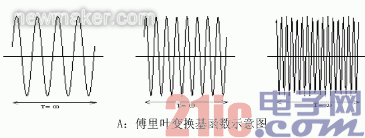

Figure 1 Schematic diagram of three transformation basis functions
It can be clearly seen from the difference of the three transformation basis functions that the basis functions of the three are actually a set of function clusters with different frequencies and different widths. The basis functions of the Fourier transform are not attenuated, short-time Fourier transforms and wavelets. Both ends of the transformed base function decay to zero quickly, so they have temporal locality. The time width of the wavelet transform is also changed, so the time-frequency resolution of the wavelet transform is also variable, with multi-resolution analysis characteristics. In this paper, the LMS wavelet analysis module is used to analyze the abnormal signal of the engine cylinder head, which reflects its powerful analysis function in non-stationary time-varying signals.
2 Analysis of the “嗒嗒†abnormal noise signal of a certain engine
The engine valve mechanism is a complex rotating machine system. The excitation and response are very complicated, and the nonlinearity is extremely strong, so that the signal to noise ratio of the vibration and noise signals picked up on the cylinder head surface is very low, and the traditional Fourier transform is very It is difficult to remove the background noise frequency, which leads to excessively masking the time-varying law in the vibration and noise signal, and it is difficult to accurately extract the information of the valve mechanism motion law. In this paper, wavelet processing is applied to the abnormal noise of a cylinder head system to accurately extract the vibration and noise characteristics of the abnormal sound, and accurately define the fault point in the engine crank angle angle domain.
2.1 Wavelet analysis for the extraction of abnormal sound signals
In the process of subjective evaluation of a vehicle NVH, the evaluator felt that there was a slight interval of “嗒嗒†abnormal noise in the car. The rhythm of this abnormal sound was very regular, which easily caused customers to perceive and complain. Through further subjective judgment, the “嗒嗒†abnormal noise comes from the upper part of the engine; in order to further investigate the cause of the “嗒嗒†abnormal noise, the abnormal sound engine is removed from the upper vehicle and then the engine is performed in the anechoic chamber. test analysis. The noise test for the near field at the top of the cylinder head is compared with the conventional Fourier transform spectrum analysis and wavelet analysis of the noise test signal, as shown in Figures 2 to 4 below. It is obvious that the spectrogram obtained by the conventional spectrum analysis in Fig. 3 does not exhibit the intermittent knocking noise corresponding to the subjective playback, while the wavelet analysis map in Fig. 4 regularly presents the intermittent tapping. signal. After wavelet analysis, the audition is played back, and the frequency of the abnormal sound at the idle speed of 760r/min is 6 times/1s, that is, the crankshaft rotates twice, and the main frequency band is concentrated at 2300-3700Hz. Corresponding to the time domain data, the wavelet analysis map has a good correspondence with the tapping time in the time domain data.
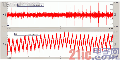
Fig. 2 Time domain data of vibration of the first cylinder intake side cam bearing housing and noise above the engine

2.2 Angle domain defines the point of failure
Through the analysis of the “嗒嗒†abnormal sound wavelet, it is basically determined that the abnormal sound comes from the valve train system. In order to further investigate the cause of the abnormal sound, it is necessary to precisely define the location of the abnormal sound. The engine crank angle analysis function provides a powerful analytical tool. In order to meet the needs of angle domain analysis, the magnetoelectric speed sensor is used to collect the engine starting tooth speed signal. Since the ring gear 132 teeth are activated, the angular domain analysis accuracy is around 3°, which satisfies the definition of the problem. At the same time, the engine 1 cylinder pressure signal is collected as a reference for the engine working cycle. Through the analysis of the angle domain of the "嗒嗒" abnormal sound signal, it is determined that the abnormal sound occurs at about 470 ° of the crank angle, and the angular signal conversion of the vibration of the valve chamber cover is further performed (see Fig. 5), and the valve is found at the crank angle of 477°. The peak of the vibration of the chamber cover is very prominent. By analyzing the angle of valve movement corresponding to the engine working cycle, it is found that the intake valve closing angle of the second cylinder is 430°, which is very close to the angle of the abnormal sound of 470°, because the valve of the VVT ​​engine is seated at the angle. There is a certain adjustment angle space, so the two-cylinder intake valve closing angle is 430 ° and a certain angle of hysteresis, close to the 470 ° abnormal sound angle. According to the initial idea of ​​the angle domain analysis, the valve is removed and the exclusion method is used to determine the source of the problem.
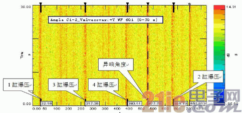
Figure 5 valve chamber cover angle domain analysis color map
2.3 Removal of valve verification angle domain analysis results
In order to verify the correctness of the angle domain analysis, the valves of 2 cylinders, 4 cylinders and all cylinders are sequentially removed in order, and then the 4 cylinders and 2 cylinder valve mechanisms are installed in order, and verified by the inspection test according to the above sequence. The accuracy of the corner test analysis. Figure 6 is a wavelet analysis time-frequency diagram of the noise above the engine after installing the 4-cylinder valve. Figure 7 shows the valve installed back to the 2-cylinder on the basis of the installation of the 4th cylinder valve. It is obvious that the abnormal sound characteristics are reproduced.
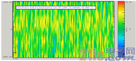
Figure 6 Wavelet analysis time-frequency diagram of noise above the engine after installing the 4-cylinder valve
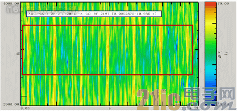
Figure 7: Time-frequency diagram of noise wavelet transform above the engine after installing the second cylinder valve
3 Conclusion
3.1 By the wavelet transform of the abnormal noise signal, the time-frequency characteristics better than the conventional spectrum analysis can be obtained, and the characteristics of the “嗒嗒†abnormal sound are found. And using the angle domain analysis to accurately locate the crank angle angle corresponding to the moment when the abnormal sound occurs, according to the engine cycle characteristics, it is pointed out that the abnormal sound comes from the seating moment of the second cylinder intake valve.
3.2 Since the engine is a complex reciprocating rotary system, many excitations have a specific relationship with the crank angle of the engine. Wavelet analysis can well reproduce such periodic characteristic signals, thus more accurately defining and judging problems. Greatly improve the efficiency of fault diagnosis. In this paper, the role of LMS wavelet analysis in time-frequency analysis is well proved by the investigation of the abnormality of the cylinder head. It also verifies the accuracy of the definition of the excitation point by the vibration domain signal in the angle domain analysis.
Our factory provides 4.3",5", 7" ,9" wired and wireless rear view mirror monitors.Really help you see the image behind your vehicle when you are reversing.
4.3/5/7/9/10.1 inch monitor has a pixel resolution of 800 x 480 /1024*600 and displayed is a sharp clear digital image. Monitor has 2 Channel Video Input; V1/V2 optional. PAL&NTSC for choose. Monitor automatically turns on and switch to Rear View Camera when reversing.
7-Inch TFT LCD screen Monitor with Built-in Wireless Receiver-- High resolution image and full color display.
Rear View Mirror Monitor,Rear View Backup Monitors,Dual Backup Camera Monitor,Rear View Backup Monitor
Shenzhen Sunveytech Co.,LTD , https://www.sunveytech.com
