This paper describes in detail the methods of making, testing and managing DC regulated power supplies. Firstly, the design of the main circuit, control circuit and simple protection circuit of DC stabilized power supply is introduced. Secondly, a method for detecting and managing each DC voltage in a complex power system with multiple voltage outputs is proposed, which can improve the voltage output detection efficiency and realize power management automation. Finally, some specific problems and solutions encountered during the design and test of the power supply are summarized. After the DC stabilized power supply is put into the field, the output voltage is stable, the load capacity is strong, and the management is convenient and fast, which satisfies the design requirements.
1 Introduction
All electronic devices must be supported by the power circuit to work properly. There is a common circuit-power circuit. Based on the characteristics of most electronic components, most electronic devices require power supply circuits to provide a continuous and stable DC power that meets the load requirements. Therefore, the design of DC stabilized power supply plays an important role in the development of electronic products. This paper mainly introduces the manufacturing method of DC stabilized power supply and the high efficiency and low cost detection and management methods of DC voltage in various systems of complex power systems.
2. DC power supply production
The design of DC stabilized power supply generally includes four basic steps of voltage transformation, rectification, filtering and voltage regulation. In order to improve the quality and reliability of the power supply, the output voltage of the power supply needs to be sampled, compared, amplified, and the error amplification signal is used to adjust its input voltage, so that the output voltage remains stable when the load changes. In addition, in order to improve the safety performance of the power supply, it is necessary to design a simple and reliable overvoltage and overcurrent protection circuit to prevent damage to the load components when the voltage and current are too large. The following is a brief introduction to the manufacturing method of the DC stabilized power supply from three aspects: the main circuit of the power supply, the control circuit, and the design of the protection circuit.
A. Main circuit design
The main circuit part design mainly includes power transformer, rectifier circuit, filter circuit and voltage regulator circuit design (Figure 1). The transformer converts the high-voltage alternating current into the required low-voltage alternating current; the rectifier turns the alternating current into a pulsating direct current; the filter filters out the alternating current component in the direct current; the regulator converts the fluctuating DC voltage into a stable direct-current voltage output (Fig. 2 ).
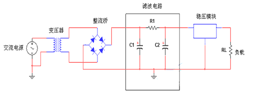
Figure 1 Schematic diagram of the main circuit
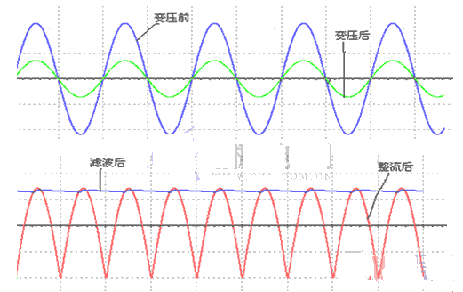
Figure 2 circuit output waveform
The working principle of the transformer is based on the law of electromagnetic induction for voltage, current and impedance transformation. In the design of DC stabilized power supply, the power transformer generally converts the single-phase power frequency AC 220V voltage into a lower voltage AC to meet the needs of subsequent circuits. According to the DC voltage and current value required by the circuit, the number of taps on the secondary side of the power transformer and the voltage and power that each tap should output are determined. In addition, in order to reduce the size and weight of the power transformer, a high frequency power transformer should be used.
The use of unidirectional conductivity of a diode to convert an alternating voltage into a unidirectional direct voltage is referred to as rectification. In the actual design, a reasonable rectification method should be selected according to the output accuracy and quality characteristics of the power supply required.
In the design of the DC stabilized power supply, the AC voltage is generally filtered by the characteristics of the voltage at both ends of the energy storage element such as the inductor and the capacitor, so that the DC power with less fluctuation is output. The DC output through the filter still contains a lot of AC components, so it cannot be directly applied to both ends of the load, and it needs to be regulated. When the Zener diode is reverse-punched, it exhibits a constant voltage characteristic within a certain current range, so it can be used to stabilize the DC output voltage. However, its power supply stability is poor, and the output accuracy is low. Therefore, a three-terminal integrated voltage regulator with stable output and reliable output is generally selected, which can shorten the design cycle and reduce the design cost under the premise of meeting the power supply design requirements.
B. Control circuit design
Only the above four basic components of the regulated power supply have poor load carrying capacity. When the load current increases, the output voltage will decrease, which cannot meet the power requirements of most electronic components. Power supply performance is typically improved by closed loop feedback control and increased output current.
In order to ensure that the output voltage of the power supply does not change with the load, the power supply itself should have feedback adjustment capability. The principle is shown in Figure 3.
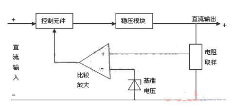
Figure 3 closed-loop regulated power supply block diagram
When the voltage across the load changes, the sampling voltage of the resistor network changes, the voltage value of the sample is compared with a given reference voltage, and the weak error signal is amplified to adjust the operating state of the control element. This adjusts the voltage across the load to keep it stable. The control component should be selected from components with adjustable operating conditions, such as a triode, whose emitter current will change with the change of the base current. Therefore, the conduction level of the triode can be adjusted by controlling the voltage of the base of the triode. Adjust the output voltage of the circuit to meet the requirements.
In addition, in order to improve the load capacity of the power supply, a triode can be used to expand the output current of the power supply, and the principle is as shown in the following figure.
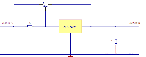
Figure 4 current expansion circuit
In Figure 4, when the load current is small, the current required by the load is completely provided by the voltage regulator module. When the load current increases, the voltage drop across the resistor R increases, which will cause the series regulator transistor Q to conduct, the transistor and the transistor. The voltage modules together provide the load current.
C. Protection circuit design
In order to improve the reliability and safety of the power supply, it is usually necessary to design some simple protection circuits, such as overvoltage and overcurrent protection, as shown in the following figure.
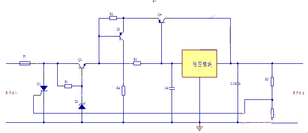
Figure 5 system protection circuit
In Figure 5, F1, Q1, R5, and R6 form an overvoltage protection circuit. When the voltage across the load rises, the voltage drop across R6 increases, the thyristor gate triggers current, the thyristor conducts, and the instantaneous large current causes F1. Fuse, thus protecting the circuit. R1, Q2, and D1 form a pre-regulator circuit, which fixes the input voltage of the voltage regulator module to a certain voltage value, so that the input voltage does not change with the load. R2, Q3, and R4 form an overcurrent protection circuit. When the current in the circuit is too large, the voltage drop across the resistor R2 increases, causing the transistor Q3 to conduct, thereby providing a path for large currents, preventing the current in the circuit from damaging the circuit. Components and volts in components. R3 and Q4 form a current expansion circuit to provide the load capacity of the circuit.
3. Power supply voltage detection and management
In a complex control system with multiple DC voltage outputs, when the system fails, it is first necessary to check whether the power output of each chip or circuit is normal. In order to avoid the time-consuming, laborious and inconvenient problems caused by manual detection, The paper proposes a simple, reliable, convenient and fast detection method for the presence or absence of DC voltage output, as shown in Figure 6.
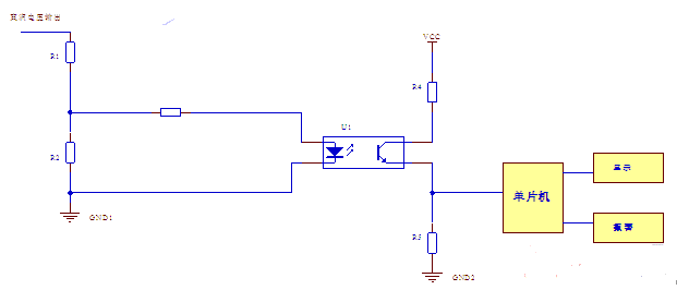
Figure 6 voltage presence or absence detection circuit
R1 and R2 form a sampling resistor network for DC output voltage. When the power supply has an output voltage, the voltage drop on R2 turns on the optocoupler, and the voltage drop on R5 increases. The high-level signal obtained on R5 is sent to the MCU. Displayed after processing. When the power supply has no output voltage, there is no voltage drop on R2, the optocoupler does not work, and the voltage on R5 is 0V. This low level signal is sent to the MCU for processing and display and alarm. Where R3 and R4 are current limiting resistors.
Under the condition that the voltage is detected or not, the circuit uses less components and is cheaper on the one hand; on the other hand, the electrical isolation of the main circuit and the control system is realized by the optocoupler, and the interference to the control system is reduced. In addition, real-time monitoring and display of the output of each voltage can easily check the normality of the power output. This method is suitable for the detection and management of complex power systems with multiple voltage outputs.
4. Problems that should be paid attention to in power supply design
The following summarizes some of the problems encountered in the power supply design and debugging process and their solutions.
Selection of power transformers. In order to reduce the volume and weight of the transformer and make it convenient to be fixed on the circuit board, a high-frequency power transformer with small size and light weight should be selected.
Selection of filter capacitors. Under the premise of meeting the volume requirement, the electrolytic capacitor with larger capacitance should be selected for filtering. In addition, the withstand voltage of the capacitor must not be less than the maximum voltage at both ends.
In the pre-regulation circuit (Fig. 5), in order to reduce the power requirement of the current limiting resistor R1, the transistor Q2 is used to provide a path for the current. In practical applications, the Q2 should use a larger power transistor.
In the circuit for current amplification with a triode (Fig. 4), the key lies in the debugging of the DC operating point of the triode, which determines the working state of the triode and determines the load capacity of the power supply.
In the design and commissioning of the entire circuit, the correct calculation of component parameters and the reasonable selection of component types are essential.
In the design process, if the simulation software can be fully combined with the verification of the working principle of the circuit, and the problems existing in the circuit can be found in time, the design cycle can be shortened and the design cost can be reduced. For heat-generating components, heat sinks should be added to prevent overheating damage. The article was originally published in the "Global Market Information Herald" magazine, No. 445, 2012, No. 08 (February 28th), sponsored by the Information Center of the Chinese Academy of Social Sciences-----Reprinted source
references
[1] Kang Huaguang, Chen Daqin. Electronic Technology Foundation Simulation Part [M]. Beijing: Higher Education Press, 1998
[2] Wang Zhaoan, Huang Jun. Power electronics technology [M]. Beijing: Mechanical Industry Press, 2000
[3] Qi Zhanqing, Wang Zhenchen. Electrical control technology [M]. Beijing: Mechanical Industry Press, 2002
[4] Zhao Jingbo. PROTEL 2004 circuit design application example [M]. Beijing: Tsinghua University Press, 2006
Wall mount fiber termination boxes are designed for either pre-connectorized cables, field installation of connectors, or field splicing of pigtails. As usual it is also called Wall Mount Termination Box.Wall Mount Fiber Termination Box can distribute cables after installing splitters and draw out room fiber optic cables in direct or cross-connections.The Fiber Termination Box is suitable for fiber terminal point to complete connection, distribution and scheduling between perimeter fiber cables and terminal equipment.
Wall Mount Fiber Termination Box
Wall Mount Fiber Termination Box,Wall Mount Termination Box,Fiber Optic Box Wall,Variable Optical Attenuator
Foclink Co., Ltd , https://www.scfiberpigtail.com
