Energy harvesting technology has been around for a long time. I still remember that in the 1980s, my pocket calculator used solar cells to power computing cells and LCD displays. Even in the early stages of the electrical revolution, power plants or generators were placed in the river mills to generate electricity and obtain available energy through the Pentium stream. Now, when we talk about energy harvesting, we generally refer to replacing batteries in electronic devices. Therefore, the 1980 Pocket Calculator example is very much in line with what we now call "energy harvesting."
Energy harvesting system settings
Obviously, the most important thing in the energy harvesting system is the collector, and the most common is the solar cell. The energy generated by the collector needs to be converted to a useful voltage or current to power the system or to charge intermediate energy storage devices such as supercapacitors and batteries. After the system is powered on, it is necessary to generate the correct voltage for the electronic device. Figure 1 shows the power management unit that meets the needs of a variety of different tasks. Match input impedances to maximize energy harvesting, charge intermediate energy storage devices, transfer electrical energy from traditional primary batteries, generate the correct output voltage for the system, and monitor current flow and voltage to form a reliable system. All of these tasks must be performed at very low power supply conditions so that the system can use small collectors or sensors. These features are highly integrated in the DC-DC converter, helping to reduce the power required for such tasks.
The system in Figure 1 shows a typical energy harvesting system for a wireless environment sensor. These sensors are commonly used to detect temperature, humidity or various gases such as carbon dioxide. There are many other applications for energy harvesting. Safety and security in wireless placeholder sensors or industrial monitoring (such as asset tracking and machine monitoring) are industrial applications.
Energy harvesting is also used in consumer electronics devices, such as portable devices and wearable devices. In home healthcare applications, wireless patient monitoring needs to be used without a battery or to extend battery life.
Energy harvesting is a very popular topic at the moment. Many engineers must evaluate whether an energy harvesting solution can replace or complement an existing energy solution. The reason why such systems are so popular today is that we have finally reached a point of equilibrium where the energy obtained from relatively low-cost and small-sized collectors is sufficient to power very low-power microcontrollers and RF circuits. In the past few years, electronic products have been upgraded and energy consumption has improved, so many applications that were not feasible 5 to 10 years ago are now available and affordable.
Figure 1. Energy Harvesting System Setup
Different energy sources
There are various sources of energy, the most common being photovoltaic (PV), thermoelectric (TEG), electromagnetic, piezoelectric and RF. Photovoltaic and thermoelectric collectors generate DC voltage, while electromagnetic, piezoelectric and RF collectors generate alternating voltage or AC voltage. This makes the requirements for power conversion technology slightly different.
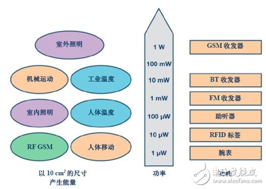
Figure 2 shows the different acquisition types and the amount of energy that can be produced by a 10 cm2 collector. The left side of the figure shows the energy generated, and the right side shows the power consumption for different tasks. Note that the middle power scale is logarithmic. This picture is very important and you can get practical design ideas. Many times, the designer's work and energy are spent evaluating energy harvesting solutions, and finally discovering that the energy collected is not enough to power a particular system.

Figure 2. Energy requirements for different energy sources and different applications
The importance of the DC-DC converter unit
Power conversion and management is often a core component of modern energy harvesting systems. Although some applications do not use complex power devices, power devices for more applications are more complex. An example of a system without intelligent power management is a chained solar cell stack that generates a relatively high DC voltage, powering the system directly or placing a simple linear regulator between them. Such systems typically do not achieve optimal energy efficiency or the supply voltage is not well regulated. While some loads can operate at varying supply voltages, others do not. In addition, more advanced systems tend to require the use of certain types of voltage converters and management modules.
Figure 3. Functional block diagram of a power management device for energy harvesting applications
Figure 3 shows a functional block diagram of a modern power management device suitable for energy harvesting applications. It contains a start-up circuit with a charge pump that causes the startup voltage on the input to be 380 mV. After the system is running, the internal circuitry of the ADP5090 is powered by the output voltage of the ADP5090. It is also the node that powers the load of the energy harvesting system. When the node is above 1.9 V, the input voltage can drop to 80 mV, but energy can still be collected. This is useful for systems that spend a lot of time in non-optimal situations, such as solar cells powered indoor sensors. Solar cells may receive less light in the morning and evening, and generate very little power. Collecting a certain amount of energy during these times is beneficial to the total power budget for a given period of time. The ADP5090 has a low quiescent current characteristic, which on the other hand improves this type of situation. It should be noted that its power consumption is only 260 nA. Figure 4 shows a typical practical application. The curve shows the different locations within the residential building and the typical time when the sensor with solar cells is in the dark. Of course, this is just a typical case. The amount of light the sensor receives depends on the structure of the house, including the number of windows, the number of lights in use, and the exact location of the sensor. In addition, the seasons of the year and the location of the house will also affect such graphics. The point is that the low power consumption of the ADP5090 is extremely helpful for the total power budget, especially for those that are in the dark for most of the time.
Figure 4. Typical time for sensors in different residential buildings to be in the dark
The DC-DC converter stage in the ADP5090 is very interesting. As with most DC-DC converters, it has a regulation loop. However, it neither regulates the output voltage nor regulates the output current. The regulation loop is primarily set in such a way as to adjust the input impedance.
The current and voltage performance of the solar cell is shown in Figure 5. Under open-loop conditions, the supplied voltage reaches a maximum when no current flows. Then, as the current flows, the voltage begins to drop. At very high currents, the voltage drops very quickly. A knee shape is formed in the middle of the curve, which is the peak power point. At this point, the voltage is still relatively high, but draws more current. In order to work at the maximum peak power point, we need to track this. Setting only one of the fixed current values ​​we have shown is not working because the curves for a particular solar cell in Figure 5 will shift according to different lighting conditions. To track the MPP (maximum peak power point), the ADP5090 stops conducting current at the input and checks the voltage without loading the solar cell voltage, then sets the next 16 seconds of MPP. After this period of time, the open loop check is performed again. 16 seconds is a good compromise, moving away from MPP and not interrupting the acquisition too often.
Figure 5. Voltage and current curves for a typical photovoltaic cell
MPP tracking ensures that most of the energy is collected from sources such as photovoltaic cells or thermoelectric generators, but the power management unit has other tasks. For example, it needs to control the output voltage within a certain voltage window. The ADP5090 is used as a current source to charge a supercapacitor or battery. This component is important for energy harvesting that consumes energy. This allows for many systems that do not have constant available energy for acquisition and perform certain system tasks at specified intervals. For example, a sensor in a wireless sensor network needs to send a temperature value every 5 minutes. If the sensor is powered by a solar cell, the system can still operate without light due to the intermediate energy storage unit.
A very popular architecture today is to incorporate energy harvesting devices into a battery-powered system. Products that use non-rechargeable batteries can successfully extend system life by adding energy harvesting capabilities. This will extend the working time without affecting the reliability of the system. For this type of hybrid system, the ADP5090 provides the ability to control primary batteries. When there is not enough energy to collect, the power path of the primary battery turns to directly supply power to the load.

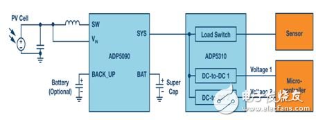
Figure 6. Example of a power management level for an energy harvesting application
Figure 6 shows a complete energy harvesting power stage that includes not only the main ADP5090 MPPT energy harvesting IC, but also a spare IC, the ADP5310. It is a DC-DC converter that produces two output voltages very efficiently. At 100 μA output current, the efficiency is close to 90%. In addition, the ADP5310 integrates a load switch. This load switch can be used to shut down loads that continue to consume energy, even if they are not being used.
The ADP5310 buck converter supports input voltages up to 15 V. Therefore, this device can be used directly in AC voltage generators, such as piezoelectric or electromagnetic generators. With a bridge rectifier, the output voltage can be fed directly into the ADP5310.
Many power management ICs are now specifically designed for energy harvesting applications. They allow the system to support smaller collectors or energy harvesting solutions that could not be designed years ago. System designers have some good ideas that are now being implemented, and we will be able to witness their implementation soon and be amazed.
Dual Function Key Switches
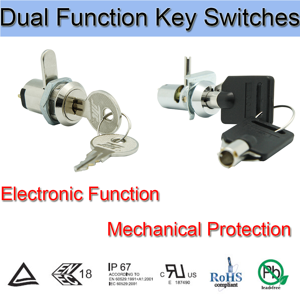
Dual Function interlock Key Switches is a Key Switches that combines Electric Key Switch and Mechanical Key Lock, which is Simultaneously have power control and could mechanically protect the equipment from invading.
Our company's Key Lock Electrical Switches has mounting dimensions of 12mm and 19mm. This 2 Position Key Switch is widely used in the field of security products, which not only can achieve the function of switching power supply but also could protect customer`s confidential data.Application including buses, cars, motorcycles, ATM and so on.

Below are the specifications:
Electrical and row piece dual function
Zinc alloy die cast housing and cylinder
Barrel chrome or nickel plated standard
Lock case, white iron cover
4 disc tumbler mechanism
Brass tubular keys or Bilateral bilateral milling copper key, nickel plated
The iron bar has a standard size of 13mm or Row Piece, can be made according to customer requirements.
Key may be withdraws in one or both position aSilver terminals and Contacts.
Dual-Function Switches,Dual Push Button Switch,Automatic Transfer Switch,Changeover Switch
YESWITCH ELECTRONICS CO., LTD. , https://www.yeswitches.com
