1 Introduction
The digital tube static display system needs to occupy too many single-chip lines, but can guarantee normal brightness. In order to solve the problem of consuming a lot of memory and wasting hardware resources, the researchers developed a series of digital tube driver chips such as the 74HC595, which can realize the serial-to-parallel operation mode and drive the digital tube to realize static and dynamic display. However, such a working method exposes problems such as insufficient real-time control system, and has certain limitations in applications where the system response time is relatively high. In order to solve the above drawbacks, this paper proposes a design scheme of digital tube dynamic display based on single chip microcomputer. The IAP15F2K61S2 series MCU is used as the control core, and the new software and hardware circuit is used to realize the dynamic display of the digital tube.
2. Control system hardware design
2.1 Display design
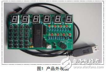
This display uses six common anode digital tubes. According to the usual practice, six digital tubes are horizontally arranged at the top of the product, as shown in Figure 1. This design can conveniently display the control status of the control system. The 40-pin DIP packaged single-chip microcomputer is used below, and all the parallel port lines are arranged with pins, which can conveniently realize the external expansion of the system and enhance the portability of the display.

The transparent acrylic material is used to make the display case, which can transmit visible light well, and at the same time, can firmly fix the circuit board.
2.2 Display Control Core
The core selection IAP15F2K61S2 single-chip microcomputer is the latest 1T single-chip microcomputer introduced by Hongjing Technology Co., Ltd. (STC) in 2013, which is an enhanced version of the conventional 51 single-chip microcomputer. The running speed of this series of single-chip microcomputer is 7-12 times faster than that of ordinary 51 single-chip microcomputer, which can greatly improve the response speed of the single-chip control system and reduce the response time of the system.
IAP15F2K61S2 MCU integrates a wealth of practical features, simplifies the hardware structure of the minimum system of the conventional MCU, eliminates the external reset circuit and clock circuit, optimizes the pin configuration, and configures five 8-bit (P0, P1, P2). , P3, P4) and a 2-bit (P5) general-purpose parallel I/O line.
The display configures the lower six bits of the P2 port of the IAP15F2K61S2 single-chip microcomputer as the selection control signal of the digital tube, and the P0 port serves as the display segment code of the digital tube to transmit the data bus.
2.3 display control circuit design
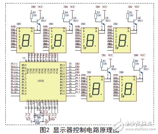
The control circuit of the display comprises a power module, a driving module, a display module, a program downloading module and the like, and the product circuit schematic diagram is shown in FIG. 2 .

The power module of the display uses two power supply methods.
The first way is to power the display through the USB to serial port downloader. The second way is to supply power through the 5V DC power adapter. In addition, it can be easily converted into 220V AC power supply. The downloader's power supply comes from the computer's USB. The current that can be supplied to the control system is too small, which affects the normal display brightness of the digital tube. The 220V AC power supply mode also needs to add too much power processing circuit, and the second mode 5V DC power adapter is used to power the display. It is convenient for powering the product and providing sufficient current.
The driving module guarantees the normal display of the common anode digital tube. Since the output current of the single-chip digital tube is limited, the control of the common end of the common anode digital tube of the P2 port needs to be added with a triode for driving. The display uses the NPN type triode 9013 to achieve the same. Digital tube public control.
The six digital tubes are horizontally arranged in a row, the common end is controlled by a triode, and the data segment is directly connected with the mouth line of the single chip microcomputer to form a display module of the display.
The download of IAP15F2K61S2 series MCU program can be realized by two pins RXD (P3.0) and TXD (P3.1) configured by its own full-duplex asynchronous serial port (UART). The hardware condition is very simple, the operation method of downloading software is very convenient, and it is favored by many MCU system developers. This display is the use of such a program download method.
Optical Filter,Long Wave Pass Filter,Optical Pass Band Filter,Bandpass Filter
Danyang Horse Optical Co., Ltd , https://www.dyhorseoptical.com
