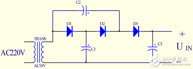
This design is to increase the input voltage UIN of the main circuit, and the rectifier filter circuit part uses a triple voltage rectification circuit, as shown in Figure 1.

Figure 1 Triple voltage rectifier circuit
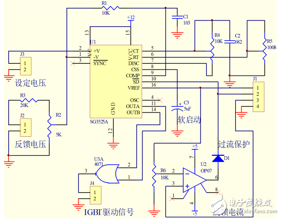
2. DC-DC converter control circuit designThe converter control part adopts the switching power supply integrated controller SG3525A, which has the advantages of wide output frequency range, wide working voltage range, high precision of reference power supply and adjustable dead time. The SG3525A has two outputs that work alternately. In this design, only one switching element needs to be controlled, so the method of driving the switching elements through the 4071 at the same time is used, as shown in Fig. 2.

Figure 2 DC-DC converter control circuit
3. Methods and implementation solutions for improving efficiency1) A step-down DC-DC converter with a simple structure and few components in the main circuit is selected as the topology.
2) Select IGBT with small saturation voltage drop and fast switching speed as the switching element.
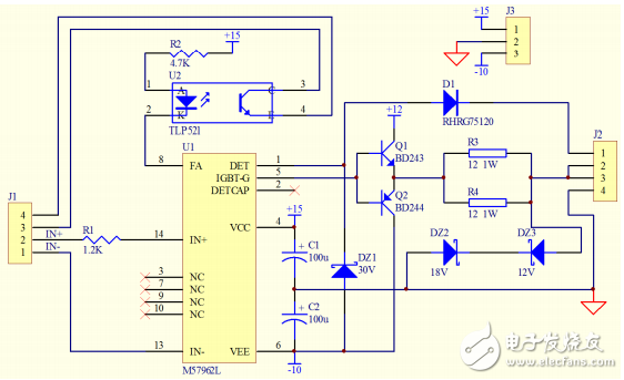
3) The M57962L is used to drive the IGBT with stable working performance and high switching speed. As shown in Figure 3:

Figure 3 IGBT drive circuit
4) Reasonably arrange the main circuit connection.
4, circuit design and parameter calculation
frame with glue,Metal Frame for iphone,Series frame with glue,Frame For Iphone x12 Pro
Shenzhen Xiangying touch photoelectric co., ltd. , https://www.starstp.com
