Abstract: This article describes the working principle and implementation of a 4-level intelligent dimmable electronic ballast circuit using the US Microchip's microcontroller PIC12F629 and the US IR company IRS2530D. The IRS2530D is a newly introduced 8-pin adjustable by IR. Optoelectronic ballast driver ICs are easy to use. The PIC12F629 is an 8-pin flash-based 8-bit microcontroller from Microchip.
1 About IRS2530D and PIC12F629
1) Introduction to IRS2530D
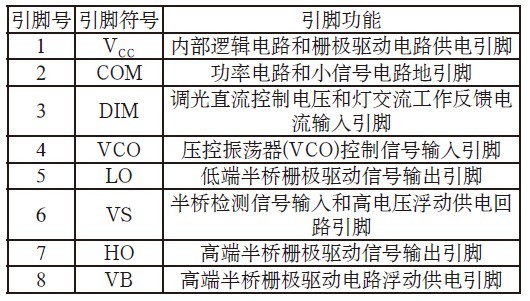
The IRS2530D is available in an 8-pin DIP or 8-lead SOIC package. The pin diagram of the IRS2530D is shown in Figure 1. The outline package of the IRS2130D is shown in Figure 2. The internal functional block diagram of the IRS2530D is shown in Figure 3. The IRS2530D is a pin. The functions are shown in Table 1.
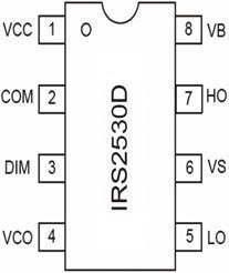
Figure 1 Pin Diagram of IRS2530D
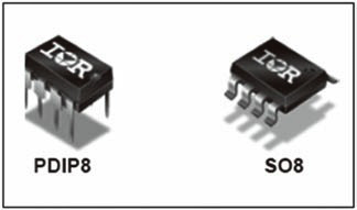
Figure 2 outline package of IRS2130D
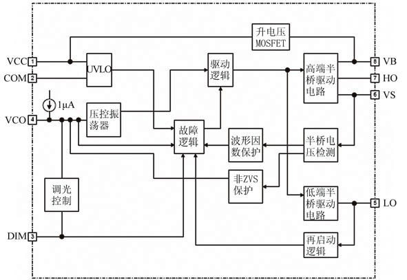
Figure 3 Internal functional block diagram of the IRS2530D
Table 1 Pin Functions of IRS2530D
2) Introduction to PIC12F629
The pin diagram of the PIC12F629 is shown in Figure 4. The pin function table of the PIC12F629 is shown in Table 2.
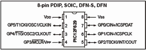
Figure 4 PIC12F629 pin diagram
Table 2 Pin Function Table of PIC12F629
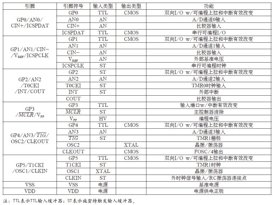
2 circuit working principle
The block diagram of the circuit working principle is shown in Figure 5. The working principle of the circuit is shown in Figure 6. The dimming control reference voltage is provided by the DIM pin of IC1 (IRS2530D), and the dimming control voltage is output by the GP2 pin of the microcontroller IC2 (PIC12F629). The GP pin of the microcontroller IC2 (PIC12F629) is general purpose I/. The O pin and I/O pin functions can be set to high impedance input or CMOS output by software. The dimming control square wave pulse voltage output from the PIC2 pin of the microcontroller IC2 (PIC12F629) is RC filtered to obtain the DC dimming control voltage required by the IRS2530D. In this circuit, the GP2 pin can output four kinds of pulse width (pulse duty ratio) dimming control square wave pulse voltage. The larger the pulse duty ratio is, the higher the DC dimming control level is.
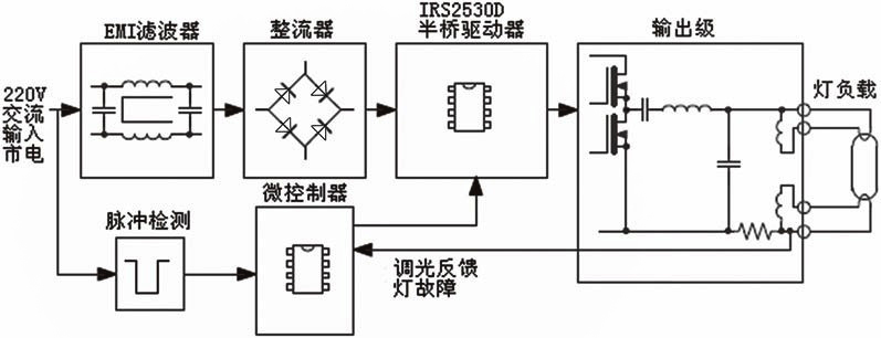
Figure 5 circuit working principle block diagram
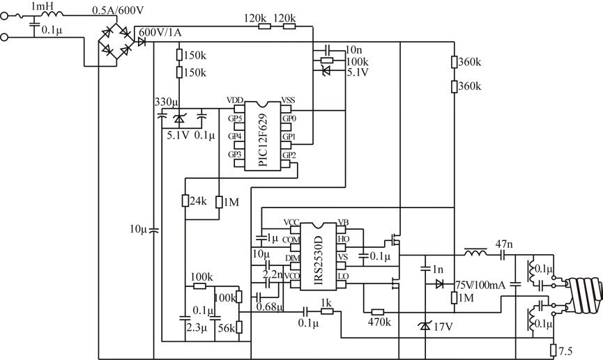
Figure 6 circuit working principle diagram
In the electronic ballast circuit shown in Fig. 6, the load of the circuit is a 25W CFL lamp load, and dimming control can be realized. The EMI filter in the circuit is used to filter out high frequency interference signals from the AC mains supply. The higher the DC dimming control level is included in the microcontroller PIC12F629.
In the electronic ballast circuit shown in Fig. 6, the load of the circuit is a 25W CFL lamp load, and dimming control can be realized. The EMI filter in the circuit is used to filter out high frequency interference signals from the AC mains supply. The PIC12F629 microcontroller contains an EEPROM that can be used to store the latest dimming set level before the mains supply is powered down. This ensures that the electronic ballast is recharged with the stored lamp brightness. The set value causes the lamp load to re-illuminate. The circuit flow chart is shown in Figure 7.
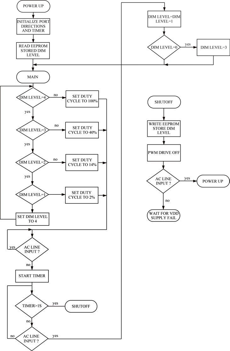
Figure 7 circuit flow chart
The GP1 input pin of the microcontroller IC 2 (PIC12F629) is connected to the 220V AC input mains supply through a filter circuit with a very short delay time. It is used to quickly detect the AC input or disconnection of the AC input power supply when 220V AC When the input mains supply is disconnected, the 5V voltage stored on the capacitor C1 for IC2 is sufficient to supply IC2 (PIC12F629) for 1s. When the 220V AC input mains supply is disconnected, IC2 detects this rapid change. And the timer starts to be timed. If the 220V AC input mains supply is restored within 1 s, the dimming level is reduced by 1 level. If the original dimming level is the lowest value, the dimming level becomes the maximum value. If the 220V AC input mains supply disconnection time exceeds 1s, the dimming level of the electronic ballast circuit does not change. When the voltage on capacitor C 1 is discharged below the minimum operating voltage VDD of microcontroller IC2 (PIC12F629), microcontroller IC2 (PIC12F629) is in the off state.
3 related circuit board diagram and physical map
The intelligent electronic ballast circuit board diagram and physical map of the 4-stage dimmable fluorescent lamp using IRS2530D are shown in Fig. 8, Fig. 9, and Fig. 10, respectively.
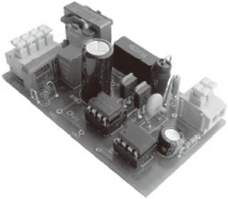
Figure 8 physical map
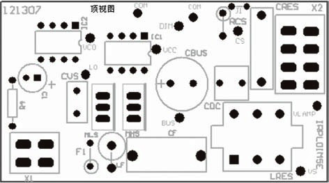
Figure 9 silk screen layer
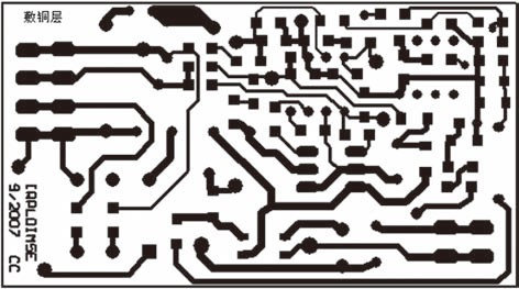
Figure 10 printed circuit board diagram
references:
[1]. PIC12F629 datasheet http://
[2]. IRS2530D datasheet http://
[3]. SOIC datasheet http://
[4]. IRS2130D datasheet http://
What is an industrial router? Which industries are they mainly used in?
With the continuous development of the network and the continuous progress of various industries, some new concepts and development directions have actually emerged during the period. For example, from the current point of view, many enterprises in the development process in order to have good efficiency and speed, as well as the use of more functions, gradually began to use industrial routers. Of course, for this type of router, we also have a lot of problems, so today we will discuss to see, what is an industrial router? Which industries are they mainly used in?
What is an industrial router?
From the basic concept, an industrial router is a wireless data transmission function that provides users with wireless data transmission through a public wireless network. For example, we use mobile phone data to transfer things to another mobile phone or computer, in fact, the principle is very simple. Of course, the specific usage operation is different. In the process of use, the industrial router has the advantage of allowing multiple users to use the same integrated network system to access the network, which is also very convenient in the work. In fact, at present, industrial routers are gradually widely used in different industries, and the practicability is also very strong.
Industrial routers are mainly used in what industries?
The first is some of the contents summarized for the concept and basic principles of industrial routers, and for the use of industrial routers, it is also some of the issues that we are concerned about. From the current point of view, the first is widely used in intelligent transportation, such as in the application of high-definition electronic bayonet, road wireless video surveillance, vehicle monitoring or security monitoring, etc., which is also very important; Secondly, it is also widely used in the financial industry, such as the use of wireless atm self-service terminals, wireless pos machines or other applications; In addition, it is the application of the power industry, such as transformer remote monitoring management, circuit line video surveillance and substation video surveillance and so on. In short, the use of industrial routers is also more extensive.
How to choose an industrial router?
Although the industrial router is widely used now, the choice we made at the beginning is still more tangled, from the feedback of the market, Movingcomm router is actually very good. According to the needs of the industry environment, based on SD-WAN+ Internet of Things, intelligent networking can then be formed into a large local area network through the cloud platform router in many places. Therefore, the focus of security monitoring can also be concentrated to complete the work of remote video surveillance, but also to meet the needs of remote working, for some of the industries we mentioned earlier, the practicality of this program is also very good. Moreover, the technology of remote networking and intelligent networking is also very mature, and the security and stability are also good. In short, the advantages of Movingcomm router are still many.
Industrial Router,Industrial 3G Router,Industrial Cellular Router,Industrial Router Din Rail
Shenzhen MovingComm Technology Co., Ltd. , https://www.szmovingcomm.com
