Abstract: This design mainly applies Zigbee wireless technology in LED lighting engineering, which solves the problem of serious power consumption and short service life of incandescent lamps. At the same time, it solves the complicated wiring, high power consumption, waste of resources and distance limitation in lighting engineering. Maintain difficult problems. Based on Zigbee technology, it has the advantages of short distance, low power consumption, low data rate, low cost and low complexity. It designs a smart home LED lighting wireless control system based on Zigbee technology. The Zigbee wireless ad hoc network technology is mainly used to realize the wireless control of the switching and brightness adjustment of the LED lights, and the functions can be divided into single lighting control and local lighting control.
At present, China has vigorously promoted the policy of replacing incandescent lamps with LED lamps, and it will be implemented within five years. This policy solves the problem of serious lighting power consumption and short service life. In addition, the engineering wiring is complicated and complicated to install, and it is difficult to move control. The problems of large consumption, long construction period and difficult maintenance in the later period still need to be solved. The wide application of Zigbee technology provides a solution to the current problems, and it is convenient and quick for family life and office buildings. Integrated management personnel achieve high efficiency and safety. In this paper, a design scheme combining Zigbee wireless ad hoc network technology and LED energy-saving lamps is proposed to realize the functions of continuous adjustment and remote control of the brightness of LED lights. The software and hardware design system is introduced in detail.
1 Zigbee wireless technology
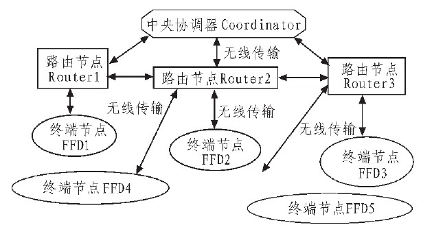
Zigbee technology is a wireless communication technology between various electronic devices used in short-range and low transmission data rates. It is a set of 802.15.4 wireless standards approved by IEEE, which determines that it can be An application outline shared between different manufacturers. Zigbee-compatible products operate at 2.4 GHz, a worldwide free open frequency band that provides 16 transmission channels, each of which automatically selects the channel with the cleanest interference minimum for data transmission. In the network layer, the star and mesh topology can be adopted. According to the different functions of the node, it can be divided into the central coordinator Coordinator, the routing node Router and the terminal node FFD. Among the three topologies, it is not easy in the star network. To implement Zigbee's advanced features, routing, each Zigbee device can only communicate directly with PANC. The mesh network is the most complex, allowing routing, and the routing path is the best path automatically calculated. After the network is established, any device fails, and the devices in the network recalculate the routing path so that the network does not affect the network. The device is communicating normally.
Therefore, the system adopts a tree network structure, which is simple and easy to implement.
1.1 Advantages and features of Zigbee
1) Low power consumption is the most advantageous place for Zigbee technology. In the communication state, the Zigbee terminal consumes several tens of milliwatts. In the power-saving mode, the power consumption is only a few tens of μW, and a dry battery can work for nearly one year.
2) Reliability: Adopt collision avoidance mechanism, and reserve dedicated time slots for communication services requiring fixed bandwidth to avoid conflicts when sending data; node modules have automatic dynamic networking function, and the information transmitted is throughout Zigbee. The network transmits by means of automatic routing, thus ensuring the reliability of information transmission.
3) Large network capacity: On the same WPAN, there can be 65 536 ZigBee devices, which can transmit information through multiple hops, and have wireless network self-healing function.
4) Large effective range: The effective range is between 10 and 75 m. If the preamplifier can reach a communication distance of 1 000 m.
5) Low cost: Zigbee data transmission rate is low, the protocol is simple and the patent fee is free, so the cost is reduced.
1.2 Zigbee Wireless Networking Principle
In the network layer, ZigBee defines three roles: The first is the central coordinator, which is responsible for establishing the network and allocating the nodes of the network; the second is the router, which is mainly responsible for finding the network and establishing And the routing path for repairing data, and responsible for transferring data, the router can communicate with the coordinator, or communicate with the terminal node, and the communication can also be performed between the routes; the third is the terminal node (FFD), which can only choose to join The formed network can send and receive data information with the router, but cannot forward information and does not have routing function. The communication diagram is shown in Figure 1.

Figure 1 Communication diagram
Working principle: Each terminal node or router in the system controls one light or multiple lights, each node has a separate network address, and the handheld control terminal sends a command to the coordinator through the wireless module, and the coordinator will receive the command. Send to each node by wireless transmission.
2 system hardware design
The implementation of the dimming function can be divided into two types: analog and pulse width modulation (PWM). When using analog dimming technology, you only need to reduce the current of the white LED to half of the maximum value, which can reduce the screen brightness by 50%. The disadvantage of this method is that the LED light color will move and the analog control signal is needed, so this The system uses PWM dimming technology. The PWM dimming technology provides a full current to the white LED, but reduces the current duty cycle to achieve dimming requirements, such as halving the brightness and providing a full current with a 50% duty cycle. The PWM signal frequency usually exceeds 100 Hz, ensuring that this pulse current is not perceived by the eye. The maximum PWM frequency depends on the start-up and reaction time of the power supply; for maximum flexibility and ease of integration, the white LED driver It should accept a PWM frequency of up to 50 kHz.
The hardware system consists of an LED lamp driver module, an LED power driver module, and a Zigbee wireless transmission module. The hardware circuit logic block diagram is shown in Figure 2.

Figure 2 is a logical block diagram of the hardware circuit.
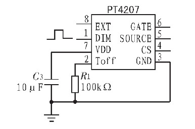
The LED lamp driver part uses the PT4207 driver chip. The PT4207 is a high-voltage step-down LED driver control chip for driving one or more LED lamps with an input voltage range of 20~450 V, which can be achieved at 85~265 VAC. Stable and reliable work within the scope and ensure the high efficiency of the system. The built-in input voltage compensation function greatly improves the stability of the LED current at different input voltages. The PT4207 also features load short circuit protection, open circuit protection and over temperature protection. Its dedicated dimming pin accepts PWM pulse dimming directly and adds a PWM signal to the DIM pin. The low level of the PWM signal is less than 0.35 V, and the high level is between 2.5 and 5 V. To achieve better dimming effect, the pulse frequency of the PWM signal is preferably less than 1% of the minimum operating frequency. The simple driving principle is shown in Figure 3. Shown.

Figure 3 shows the drive schematic of the PT4207.
The Zigbee wireless communication module is based on the CC2530.CC2530, a true system-on-a-chip (SoC) solution for 2.4-GHz IEEE 802.15.4, ZigBee and RF4CE applications. It has extremely high receiver sensitivity and immunity to interference, enabling the creation of powerful network nodes at very low total material costs. The CC2530 combines the performance of leading RF transceivers with an industry-standard enhanced 8051 CPU, in-system programmable flash, 8-KB RAM and many other powerful features. The CC2530 has four different flash versions of 32/64/128/256KB, and the system uses 256KB of flash memory. The CC2530 has different operating modes, making it especially suitable for systems with ultra-low power requirements. The short transition time between operating modes further ensures low energy consumption. The system changes the brightness of the light by changing the PWM output. The Timer 1 of the CC2530 is a 16-bit timer with timer/PWM function. It has a programmable divider, a 16-bit period value, and five respective programmable counter/capture channels, each with a 16-bit compare value. A 16-bit capture register is also used to record the exact time at which a frame start delimiter is received/transmitted, or the exact time at which the transfer ends, and a 16-bit output compare register can generate different strobe commands at specific times (start RX) , start TX, etc.) to the wireless module. Each counter capture channel can be used as a PWM output or as a capture of the input signal edge timing. Timer 2 is designed to support IEEE802.15.4 MAC or other time slots in software. Timer 3 and Timer 4 are 8-bit timers with Timer/Counter/PWM functionality.
3 system software design
The software development environment selects IAR Embedded Workbench for MCS-51 7.51A as the IDE developed by Zigbee. Based on the TI Z Stack protocol stack, the application code of the system is written, and the upper computer program is written by VC.
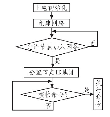
Z Stack provides a rich debug function debug interface. The system software mainly includes a coordinator node program and a router node program. The coordinator is the first-level node, which is responsible for setting up the network. After the network is set up, the node ID address is assigned. The coordinator receives the command sent by the handheld control terminal, and sends a control command to the node to implement the corresponding control. Figure 4 is the coordinator. Work flow chart.

Figure 4 Coordinator work flow chart.
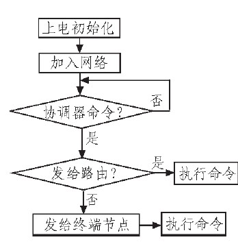
The following extensions to Level 2, Level 3, and even multiple levels, as long as the corresponding control can be implemented on the same network, the coordinator receives the command and sends the control command to the router or the terminal node. If the command is sent directly to the router, the router executes The corresponding command can also be sent to the terminal node through the router, and the terminal node executes the corresponding command. Figure 5 shows the workflow of the router (including the terminal node).

Figure 5 shows the workflow of the router (including the terminal node).
4 function realization
The control terminal is a handheld remote controller. The wireless transceiver module is set in the remote controller. When the network is set up, the remote controller is added to the network. The remote controller automatically recognizes the ID address of each node and controls by sending commands to the nodes. The brightness of a single lamp can be adjusted, that is, a control command is sent to a single node, or a part of the node can be set up to store a local area network to the remote controller, and a command can be sent to the local area network to implement light control of all nodes in the local area network.
5 Conclusion.
Through the Zigbee technology, the wireless control of the light is realized, which solves the problems of complicated wiring, poor expansion, high price, high power consumption and blind area in the communication range of the home intranet, realizing wireless communication in the home or office, and the control is constructed. The system has the characteristics of low power consumption, low cost, easy development, easy expansion, and control by the hand-held remote control. Due to the country's vigorous use of LED energy-saving lighting, Zigbee has a broad market for wireless lighting control, and can be further extended to wireless control of home appliances in smart homes, and even remote wireless control. Based on the various advantages of Zigbee technology, there will be a lot of room for development on the Internet of Things, especially in school dorms, teaching buildings, libraries or canteens.
An Audio Cable, referred to as an audio cable, is used to transmit electrical acoustic signals or data. Broadly speaking, there are two major categories of electrical signals and optical signals. The line that the audio cable uses to spread the sound. It consists of two parts: the audio cable and the connector. The audio cable is usually a two-core Shielded Cable. The common connectors are RCA (commonly known as lotus head), XLR (commonly known as card head), and TRS JACKS (commonly known as plug head).
Chinese name
Audio Lineeffect
Used to transmit electroacoustic signals or data
Generalized classification
Electrical and optical signals
composition
Audio cable and connector
Full name
Audio cable
connection method
Balanced connection, unbalanced connection
classification
Audio electric signal cable, audio optical signal cable
Audio Cable
Audio Cable,Optical Audio Cable,Digital Optical Audio Cable,Rca Audio Cable
Jiangsu QiSheng Cable Co., Ltd. , https://www.shuaihe-cable.com
