In the real world, Power means money - the bigger the better, and the opposite for μC peripherals. With the continuous development of the consumer market, the volume of terminal application products continues to shrink, and the Power (power) is as small as possible. It's no surprise that portability and low power consumption are top priorities and industry trends that drive processor core voltages down to 1.8 v. Although these low-power devices consume much less energy than the 3.3 v and 5 v models, the low-power processors are not all the same. Designing a low-power application requires both the end-use requirements and the various μC features available.
This article refers to the address: http://
Designers may ask the following questions: Can you recharge? How small can the size be? What is the typical working time? How fast must it be? What type of peripheral device do you want to connect to? These answers will eventually accumulate the original data for establishing design criteria and power requirements.

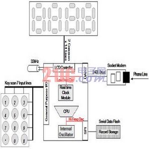
Figure 1: Device Processing Power in a Typical μC Environment
First, you should consider the processing power of the CPU. In general, the CPU is the most power-consuming peripheral device. When the processor is running at full speed, the power consumption is very large, so the more time the CPU is in standby or off state, the longer the battery life. For example, a 4-bit processor has lower power consumption than a 32-bit processor; a processor with any number of bits in a sleep or shutdown state consumes less power than a working processor. Therefore, if a 32-bit processor takes only 1/10 of the time to execute a function, it consumes 9/10 less power over the life of the system. Therefore, most manufacturers recommend running the CPU at a higher frequency, completing the task quickly, and immediately returning to the lowest power sleep state. In summary, when choosing a processor speed, consider the ability to quickly process the expected workload and sleep as long as possible.
Second, consider the Interrupt Service Routine (ISR) for most portable applications. The ISR periodically wakes up the processor to perform a pre-programmed or user-initiated task and then returns the processor to sleep. The fewer CPU clock cycles used to enter and exit the ISR, the better. In fact, many ISRs (such as port I/O) have multiple flags that may trigger the same interrupt. Processors that use program counter relative addressing greatly reduce the number of cycles required to identify and process appropriate interrupt sources—especially in keyboard scanning applications. If the ISR is well written, the processing time is minimized by limiting the program branches needed to wake up the CPU, perform tasks, and return to sleep. In processors that use the interrupt vector table, the program counter loads the ISR address, which helps reduce additional program branching and reduces power consumption. Automatic context saving and recovery of the arithmetic logic unit (ALU) flag and power mode can also promote energy savings.
In addition, since the dynamic core processor cannot maintain data integrity in low-speed or clock-stop environments, static kernel processors should be used whenever possible.
Operating mode
Sleep and "low power" modes are also important issues that must be considered. Achieving a low-power state by slowing down the wake-up time (or turning off a function that is important to wake-up devices) increases power consumption rather than reducing power consumption.
The sleep or idle mode of most low-power devices shuts down the processor and clock, typically with less than one microamp. Then, an I/O interrupt is required to wake the processor from sleep mode. Using a 32kHz clock to drive a timer or a real-time clock can wake up the processor in a more flexible way. The power consumption based on the 32kHz oscillator is not as low as the "deep sleep" mode, but it can provide clocking with a few microamps of current. Since many portable applications require real-time clocking, this improvement allows the system to choose from a variety of different peripherals.
One thing to note is that if the processor must wake up from a shutdown state using the RESET signal, it must run all hardware initialization routines. In fact, even if the contents of the processor SRAM are not changed and the interrupt can still be addressed, it will have to reinitialize the processor peripherals, which will consume energy.
Oscillator
When waking up by a reset, the internal oscillator can execute nearly 1,000 instructions more than the external oscillator due to the time it takes to stabilize the oscillator crystal. For example, a 100 MIP machine using an external oscillator takes up to 1 millisecond to start, stabilize, and process instructions. In contrast, the same machine takes only one microsecond to operate the internal oscillator at full speed. When the external oscillator is stable, the internal oscillator can be powered up, execute 1000 instructions, and then resume power-down. This time is usually enough to find the interrupt address and restore the power down state. So why consider using an external oscillator? External oscillators are typically more accurate over the entire operating temperature range. In fact, in low-power applications, embedded program devices are often accustomed to calibrating the internal oscillator against an external oscillator. This is because the circuit required to drive the external oscillator and bring it to speed is more powerful than the internal oscillator.
Care should be taken when selecting the internal oscillator. Although some internal oscillators can wake up the processor in microseconds, it must take a few milliseconds to run at a higher speed when the external crystal is stable before the CPU clock can switch to a higher frequency. For example, if a 100 MIP processor has a 20 kHz internal clock that is enabled simultaneously with the external oscillator's 1 MHz clock, the internal oscillator will still be able to execute 999 instructions, while higher speed processors will use the same time. Only 20 instructions can be executed.
Timer
Using a good timer helps to implement system processing while the processor is in standby. This helps to greatly reduce power consumption due to the very small power consumption of the timer. The real-time clock module should accept the 32kHz timer timer input and set an "alarm" or interrupt for different time intervals to increase the timer count without processor intervention. Again, shadow registers should be used to update and compare values ​​from the ISR. Once the register reads a valid preprogrammed value, the ISR is triggered to put the processor out of sleep or standby without the CPU looking for an ISR address, update cycle, or compare value.
Management overhead
Management overhead System monitoring procedures and monitoring work help to prevent unsafe conditions, including voltage monitors and watchdog timers. Since the digital circuit relies on a flip-flop or a transition from a negative to a positive (or vice versa) state, even if the operating voltage has a slight drop, the RESET condition may be accidentally triggered, causing the system to fail. Power-down protection is part of voltage monitoring and is typically used to ensure that voltage transients do not force the processor into and out of the RESET state.
Whenever possible, non-maskable interrupts (NMI) should be used in voltage monitoring solutions to identify voltage transients. This approach allows the user to set the voltage-triggered threshold level as desired, without the need for a system reset condition, and typically consumes less power than an analog-to-digital converter (ADC) channel.
The watchdog timer monitors for fault conditions. Although embedded system programmers often disable the watchdog timer in typical embedded applications, in low-power systems, the watchdog timer is useful in situations where the supply voltage is unstable. tool. The watchdog timer performs pre-set functions, such as issuing a RESET command to the processor when certain conditions are met, such as a low voltage or a memory problem. The selected processor should be able to generate a known ISR so that the processor can be brought back online without performing a RESET; because RESET is performed, the peripheral must be started and thus consume more processor power.
UART communication
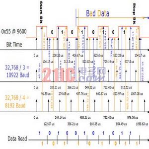
It is not possible to synchronize one digital clock with another digital clock to the nearest second because each clock is synchronized with its internal crystal. In an MCU-driven system, a similar synchronization problem occurs between the 32kHz real-time clock crystal used in low-power mode and the normal 38.4kHz frequency used to generate the UART baud rate. Because the 32,768 frequency of the real-time clock causes the 15-bit register to overflow once per second, it is ideal for time-keeping applications. In comparison, using the same frequency in the UART guarantees that at least one bit is read incorrectly in a typical 10-bit (start bit, 8-bit data, and 1 parity bit) transfer. This is because the 32,768 Hz clock must be divided by 3.4 to get a 9,600 baud rate. Since there is no 3.4 option, you must choose to divide by 3 or divide by 4 (see Figure 2).
It is not possible to synchronize one digital clock with another digital clock to the nearest second because each clock is synchronized with its internal crystal. In an MCU-driven system, a similar synchronization problem occurs between the 32kHz real-time clock crystal used in low-power mode and the normal 38.4kHz frequency used to generate the UART baud rate. Because the 32,768 frequency of the real-time clock causes the 15-bit register to overflow once per second, it is ideal for time-keeping applications. In comparison, using the same frequency in the UART guarantees that at least one bit is read incorrectly in a typical 10-bit (start bit, 8-bit data, and 1 parity bit) transfer. This is because the 32,768 Hz clock must be divided by 3.4 to get a 9,600 baud rate. Since there is no 3.4 option, you must choose to divide by 3 or divide by 4 (see Figure 2).

Figure 2: 32Khz Drive UART Rx Error on 9600 baud Transfer
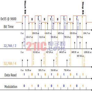
The UART data is received with a 10,922 baud or 8,192 baud UART. Since the UART samples the data at the midpoint of the transmission to compensate for the jitter, this point has been selected to receive the sample point of the UART. In the ideal case of no line jitter, the 10,922 baud UART will be wrong for the first two readings of the third data bit and the 8,192 baud UART will quickly miss the third bit because it will completely miss the third bit. Since the ideal clock for low power applications is the low power real time clock mode, this makes processing in low power environments difficult. The best way to solve this problem is to combine μC with modulation techniques to provide a very accurate 2,400 baud with a 32 kHz oscillator and fully support 9,600 baud (see Figure 3).

Figure 3: 32Khz Driver UART with Clock Modulation at 9600 baud Transmission
By mixing the two clock divisors to resolve the error, the overall accumulated error disappears and the data is received correctly. This method is effective for UART communication of 9,600 baud or less. For high-speed communication, several μCs monitor the edge transitions of the UART Rx line and trigger the ISR to start the internal high-speed oscillator, drive the CPU and handle the interrupt. This allows the μC UART to receive high speed data without having to keep a starting high speed clock during UART idle. If the external oscillator is used or the internal oscillator frequency is too low, the first transfer will fail due to the time required to start the high speed oscillator. To overcome this limitation and loss of efficiency, designers should consider using a processor that wakes up and activates in time from 32kHz or shutdown mode to recover the first transmitted data from the UART being transmitted. For example, the system clock needs to be started within 25μs to pick up the midpoint of the start bit to correctly receive a 19,200-bit transfer.
Many low-power applications connect the μC to the RS-485 sensor network via a UART. UARTs that support addressing and multiprocessor (9-bit) mode are well suited for this type of network. When the 9th bit is 1 (representing an address), these UARTs generate an ISR that allows the processor to remain dormant while other sensors are transmitting data through the system. Some μCs go a step further by adding an address match in the UART, which wakes up the system only when the 9th bit is 1 and the address matches the data received in the remaining 8 bits.
Analog device
Analog device analog devices are the first operating devices. Analog devices have been in development for decades and are essential for stabilizing power supplies, providing filtering and stability for high-speed crystal circuits, and are essential for monitoring input signals from nature.
Analog device analog devices are the first operating devices. Analog devices have been in development for decades and are essential for stabilizing power supplies, providing filtering and stability for high-speed crystal circuits, and are essential for monitoring input signals from nature.
In standby mode, the analog device does not actually consume power. The analog-to-digital converter (ADC) is powered down quickly and can even be considered a low-power application in standby mode.
Once power is applied, the shortcomings are exposed. In general, analog devices require a large amount of current during operation. For example, the ADC requires hundreds of microamps of current to operate. In addition, analog devices (such as the internal reference clock) increase the startup time by a few milliseconds because stable analog devices require relatively large external capacitance. Another device that is often integrated - an integrated temperature sensor - is usually a diode circuit that changes with temperature and requires a considerable amount of current.
There are several criteria to consider in low power applications. If the ADC has an internal oscillator, there is no need to power up other system oscillators for conversion. In this case, the processor remains powered down and needs to start working only when the conversion is complete. Like the CPU, we can reduce power consumption by reducing execution time. The faster the ADC converts, the faster the device enters standby mode. The same is true for the internal reference clock. The faster the reference clock starts and stabilizes, the faster the conversion is completed and the analog system is powered down. If the ADC is only used occasionally, some processors allow the sample clock to be powered down, leaving the tracking circuit powered. This allows the ADC to enter a shallower sleep mode. The downside of this feature is that it takes a long time to stabilize the sample and hold circuitry before the conversion takes place.
After the conversion is complete, several μCs integrate direct memory access (DMA) or first-in, first-out (FIFO) buffer memory to store multiple conversions in RAM without waking up the processor. The processor stays in standby until a certain number of conversions arrive, rather than waking up the processor after each conversion to move data into RAM, which reduces power consumption.
Many low-power μCs have built-in internal analog comparators that perform simple simulation tasks. Some manufacturers' comparators allow programming and can reduce power consumption by extending response time.
Starting point
In summary, the choice of μC peripherals is ultimately determined by the end application, so we should start with a comprehensive assessment of system functionality and its power requirements. Many processor manufacturers claim that their devices have low-power operation, but different applications have different definitions of the term "low power." Is it a higher speed processor that requires a lot of integration, or a lower speed processor that requires a very deep sleep mode, more depending on the requirements of the embedded system, rather than the so-called "low power consumption of the embedded processor? "Ability to work.
Ac Electronic Centrifugal Switch Board,Motor Accessories Board,Centrifugal Switch Gear,Electric Motor Centrifugal Switch Accessories
Ningbo Zhenhai Rongda Electrical Appliance Co., Ltd. , https://www.centrifugalswitch.com
