Today, MPS Xiaobian wants to talk to you about the power management strategy in charging IC: dynamic path management
Dynamic path management dynamically adjusts the charging current based on the capabilities of the input power supply and the level of the load current, thereby minimizing the charging time while ensuring system power usage. In addition, dynamic path management also ensures that when the battery is over-discharged, the system can be started immediately after the input power is plugged in.
In rechargeable mobile devices, the charging IC is an essential component. Depending on how the battery is connected to the system load, the system load can be powered by the input power source, battery powered, or both. Then the battery IC must have power management functions to achieve the choice of system load power source.
Narrow Voltage DC (NVDC) dynamic path management
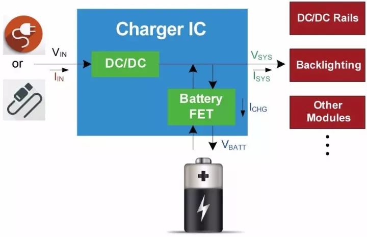
NVDC dynamic path management is one of the power management strategies commonly used in mobile devices. As shown in Figure 1, the system load is directly connected to the system bus VSYS. The system load can be directly powered by the battery through the Battery FET, or by the input power through the front-end DC/DC.

figure 1
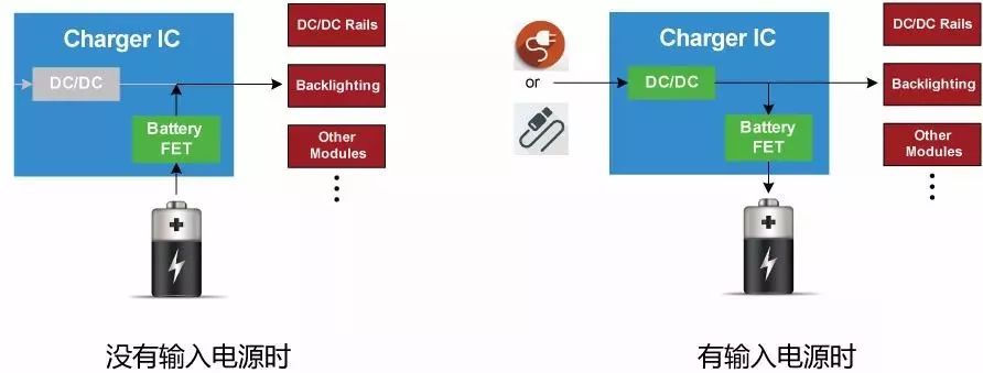
When the input power is not connected, the Battery FET is fully turned on and the battery directly supplies power to the system load. When there is input power, the system bus voltage is regulated by DC/DC, and the system bus charges the battery through the Battery FET. However, the system load has a higher power priority. The charging IC preferentially powers the system based on the capabilities of the input power source and the system load, and the remaining power is used to charge the battery.

figure 2
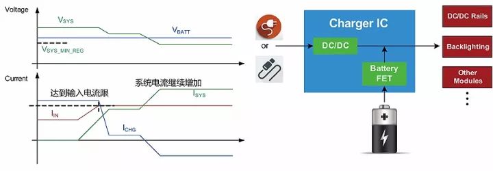
During the above charging process, when the total system load demand (including battery charging demand) exceeds the capacity of the input power supply, the system bus voltage will drop, and the charging IC will reduce the charging current to ensure that the total load power will not continue to increase. Therefore, the system voltage is no longer dropped, and the system load is maintained smoothly.
If the input power still fails to meet the system load demand after the charge current is reduced to zero, the system bus voltage will continue to drop until it is lower than the battery voltage. At this time, the battery will supply power to the system through the Battery FET, which is called the battery replenishment mode. At this point, the input power and battery provide power to the system at the same time.

image 3
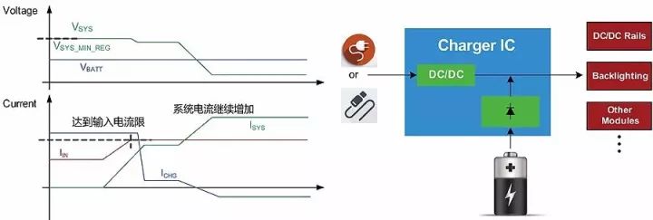
When there is input power and the battery is over-discharged, the charging IC will adjust the system bus voltage to a minimum supply voltage that is acceptable for a system load. When the system voltage is below a certain threshold, the charging current will decrease. When the battery is reversely discharged, the charging IC controls the battery FET to operate in the saturation region according to the battery voltage, avoiding a large inrush current flowing into the over-discharged battery. This smooth entry and exit of the battery supplemental power supply mode is commonly referred to as Battery. The ideal diode mode for FETs.

Figure 4
In the ideal diode mode, the Battery FET is similar in characteristics to a diode due to its operation in the saturation region. When there is input power and the system voltage is lower than the battery voltage specific value (for example, 40mV), the charging IC adjusts the gate of the Battery FET to control the voltage difference between the battery and the system voltage to a specific value (for example, 20mV, equal to an ideal diode tube). Pressure drop). As the battery discharge current continues to increase, the gate voltage of the Battery FET rises to reduce the impedance of the Battery FET, thereby ensuring that the voltage difference between the battery and the system remains at design value until fully turned on. Conversely, if the discharge current is reduced, the gate voltage of the Battery FET is lowered to increase the impedance of the Battery FET, thereby adjusting the voltage difference between the battery and the system to maintain the design value.
to sum up:
Dynamic path management control is complex, but has many advantages:
First, the system voltage can be established immediately after the input power is inserted, regardless of whether the battery is over-discharged.
Secondly, the flexible adjustment of the charging current allows the energy requirements of the system to be prioritized.
1.00mm Female Header Connector
1.00Mm Female Header Connector,1.00Mm Dip Vertical Type Connector,1.00Mm Smt Right Angle Type Connector,1.00Mm Smt Double Row Stand-Off Connectors
Shenzhen CGE Electronic Co.,Ltd , https://www.cgeconnector.com
