In recent years, the electrification of the global transportation sector has developed rapidly. By the end of 2012, the number of electric vehicles (EVs) worldwide has reached approximately 180,000 units. According to the International Energy Agency's (IEA) Global Electric Vehicle Outlook report, this figure increased by 3.7 times at the end of 2014 to more than 665,000 vehicles. The report also predicts that approximately 20 million electric vehicles will be used on the road by 2020.
With the rapid growth of electric vehicles, in order to extend the mileage of vehicles, the demand for charging infrastructure has also risen. An electric vehicle charging station, also known as an electric vehicle supply unit (EVSE), powers electric vehicles while providing network interconnection. In this article, electric vehicles (EVs) include rechargeable electric vehicles or pure electric vehicles (BEVs), electric buses, and plug-in hybrid vehicles (PHEVs). Figure 1 shows a working electric vehicle charging station.
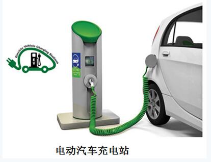
Figure 1 This is a common scenario where an electric car is charging at a charging station.
The IHS Automotive Division predicts that the global installed capacity of electric vehicle charging stations will increase from 1 million in 2014 to 13.6 million in 2020. According to this market research company, the installed capacity in the Americas will reach 4.3 million by the time; the installed capacity in Europe, Middle East and Africa (EMEA) will reach 4.1 million; the installed capacity in Asia (including Japan) will reach 5.3 million.
Governments such as Germany, China and the United States are gradually investing more money in developing charging infrastructure. For example, China plans to build 4.5 million electric vehicle charging stations by 2020. According to the China Central Government website, this will help achieve the goal of increasing the cumulative production and sales of pure electric vehicles and plug-in hybrid vehicles to 5 million units by 2020. Based on the fact that 31,000 charging stations were built at the end of 2014 [Note 5], the goal of building 4.5 million charging stations means that the compound annual growth rate (CAGR) needs to reach 129%.
The charging station standard brings a wide market opportunity to the electric vehicle charging infrastructure, but also brings serious challenges that need to be solved. One of the challenges is the lack of uniform standards for key components of the charging system, such as charging lines, protection mechanisms, power ratings, plug types, coupler configurations, and communications. These problems are more pronounced in fast charging systems than in AC slow charging because fast charging systems are typically installed in shared public or semi-public areas. Obviously, system incompatibility can make sharing difficult.
The International Electrotechnical Commission (IEC) has created a set of standards covering the charging of electric vehicles. For example, IEC 61851-1:2010 EV is suitable for both in-vehicle and off-vehicle equipment that charge electric vehicles up to 1000 V AC and up to 1500 V DC. IEC 61851-23:2014 specifies the requirements for DC electric vehicle charging stations. In addition, IEC 62196-3:2014 specifies specific requirements for electric vehicle charging couplers.
On a global scale, fast charging systems are currently facing competing standards – one is the CHAdeMO agreement adopted by the Japanese industry, and the other is the American and German car manufacturers, adopted by the International Society of Automated Engineers (SAE International). J1772 Joint Charging System Standard (CCS, also known as the "Combo" standard). These standards differ in specifications for rated power, coupler design, and communication protocols between EVSE and EV.
However, it has also been pointed out that "there is no standard dispute" because their charging system design integrates all functions and meets CHAdeMO and SAE standards. An example of this is ABB's Terra 53 charging station. Another relatively new competitive standard is the revised version of GB/T 20234, which was approved by China in recent days. Some designs, such as Tesla's super charging station, use specialized charging techniques.
AC or DC charging?
Regardless of the complexity of the standard, there are currently two main ways to transfer electricity from outside the vehicle to the battery inside the vehicle: alternating current (ac) or direct current (dc). The grid is powered by AC, while the one stored in the vehicle battery is DC. Therefore, a charger is required for the conversion work.
Depending on whether the charger is installed inside or outside the vehicle, it can be divided into an on-board charger (OBC) and an off-board charging station. The car charger accepts AC power from the main power source at home and in the consumer's workplace and converts it to DC for battery charging. Normally, the AC charging speed is slow because the allowable power rating of this charger is limited - this is due to the allowable weight, space and cost.
DC charging is commonly used in off-board charging stations. It injects direct current directly into the battery inside the vehicle. Since the DC charging device is installed in a fixed position and has no size limit, it can be rated up to hundreds of kilowatts.
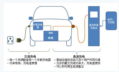
Figure 2 DC fast charging method reduces charging time from hour to minute
For example, the SAE J1772 standard increases the DC Level 2 specification to 100 kW. The CHAdeMO standard considers 50 kW as the best output power, taking into account the cost of getting the maximum power at the charging station location and the charging time of the battery. Tesla's super charging station consists of multiple Model S chargers working in parallel, delivering up to 120 kW of DC power to the battery. This charging speed is equivalent to the power required to travel 170 miles in about 30 minutes. The DC fast charging method reduces the charging time from the hour to the minute. Figure 2 shows both AC and DC charging methods. The table below lists the maximum allowable charging power and estimated charging time for AC and DC charging for your reference.
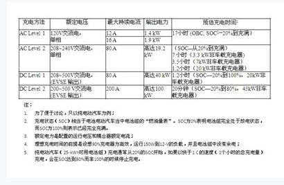
The charging speeds of alternating current (ac) and direct current (dc) chargers vary, and both are critical to adapting to the different lifestyles of electric vehicle drivers. For example, an electric car driver can use AC charging when there is plenty of time, such as when staying at home or at work. In contrast, DC fast charging can greatly reduce charging time so that electric car drivers can continue their journey faster. Fast charging is a key factor in the successful introduction of electric vehicles that reduce customer mileage anxiety, especially long-distance driving.
The charging station topology and the safe isolation of all functions of the in-vehicle electronic system of the electric vehicle charging station and the electric vehicle charging station need to take into account the need for safety isolation. The in-vehicle system includes a high-voltage battery management system, a dc-dc converter, a motor-driven inverter, and a car charger. For in-vehicle systems, optocouplers must have better reliability and safety in isolation, including gate drive, current/voltage sensing, and digital communications. The discussion in this article will focus on isolation solutions for off-board charging station designs, often with industrial grades.
In general, an electric vehicle charging station typically includes functional blocks including an AC-DC rectifier, a power factor correction (PFC), and a DC-DC converter to regulate the voltage to a level suitable for charging the vehicle battery. Figure 3 is a simplified diagram of the functional block design of a DC charging station. In high frequency isolated topologies, electrical isolation is provided in the dc-dc converter by high frequency transformers. In addition, multiple isolation devices provide a variety of signal isolation features while maintaining safe isolation between high voltage electrical and low voltage controllers. In all of these parts, MOSFET and IGBT power devices are used to perform the switching function.
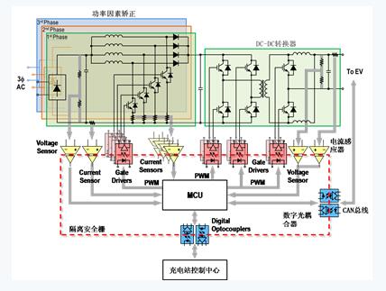
Figure 3 Charge Control Center performs calculations and executes control commands to implement design functions
Located at the center of the system is the Micro Control Unit (MCU), which controls Power Factor Correction (PFC) and dc-dc converters with Pulse Width Modulation (PWM) signals. The charge control system performs calculations and executes control commands based on voltage and current information and other data such as temperature and user input to achieve the designed function. The digital communication port is used for communication between the EVSE and the electric vehicle charging control center, and then accesses the cloud for reporting charging data, remote monitoring and diagnosis.
The optocoupler provides galvanic isolation and efficient charging. As shown in Figure 3, the isolated barrier is built along the line formed by the coupling points of multiple optocouplers. This is important in ensuring that the design meets safety regulatory standards. In addition to electrical isolation, another important factor that needs to be focused on including power converters in EV charging stations in power converters is power conversion efficiency. This article describes how to use several optocouplers in the catalog [Note 17] to implement an efficient charging station design and ensure safe isolation.
Gate Driver In an electric vehicle charging station, the MCU changes the PWM signal to turn the MOSFET or IGBT on or off and adjust the duration of each state to adjust the output voltage/current according to the battery charging mode. The PWM signal output from the MCU typically needs to be amplified to increase the output current and switch the electronics at the desired frequency. This is achieved by driving a MOSFET or IGBT gate using a device called a "gate driver."
Currently, some gate driver vendors offer a complete portfolio of products, from basic gate drivers to feature-rich integrated gate drivers to meet the design needs of efficient drive and protection functions. For example, the ACPL-W346 gate driver provides 2.5 A output current, rail-to-rail output voltage range, and extremely short 55-ns propagation delay time. These electrical specifications are essential for designs that require high power conversion efficiency. This part is packaged in SSO-6 small surface mount devices with a rated insulation voltage of 5000 VRMS per minute according to UL1577 standard and 1140 VPEAK according to IEC / EN / DIN EN 60747-5-5. Passing these standards means that the security of the controller and the user will be guaranteed.
In the design of electric vehicle charging stations, in addition to choosing the best power conversion topology, the choice of advanced power devices and appropriate gate drivers can help achieve efficiency goals. Silicon carbide (SiC) MOSFETs are rapidly emerging in the commercial power equipment market, offering several benefits over traditional silicon-based MOSFETs and IGBTs. One of the benefits is reduced switching losses because high voltage SiC MOSFETs do not suffer from tail current losses in IGBTs. In addition, SiC MOSFETs have high current densities and small cell sizes, and have lower capacitance than silicon MOSFETs. Therefore, a higher switching frequency can be achieved, thereby increasing the efficiency of the system.
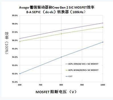
Figure 4 Improves efficiency with Avago gate drive and Cree SiC MosfETs
The experimental results show that the efficiency improvement is quite significant. These designs use AC PL-W346 and ACPL-339J with appropriate buffer steps and cooperate with Cree C2M SiC MOSFETs in 8-A, 100-kHz SEPIC dc-dc converters. When the blocking voltage is 600-V, the SiC MOSFET-based system is 4% more efficient than conventional IGBT-based designs (Figure 4). Figure 5 shows a simplified connection loop for driving a SiC MOSFET using ACPL-339J.
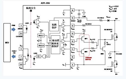
Figure 5 This figure shows a simplified connection loop using ACPL-339J to drive a SiC MOSFET.
Voltage and Current Detection There are three main ways to charge the battery of an electric vehicle: constant voltage, constant current, and a combination of the two. Most electric vehicle charging systems use a constant voltage during the initial stages of the charging process and then use constant current charging in the final stage. In order to effectively use these charging methods, the voltage of each node and the current of several shunts need to be measured and fed back to the MCU for calculation, thereby adjusting the PWM signal accordingly. For example, in Figure 3, the DC link and charger output voltages need to be continuously monitored and ensure accurate readings. In addition to voltage information, the PFC system – the power passing through the input and output rails – also needs to be measured.
Many studies on high-efficiency charging systems use voltage and current information as basic parameters in control algorithms and power calculations—the accuracy of information in such calculations is critical. The charging voltage, current and charging time constitute the energy consumption during the charging process, which in turn translates into a charging bill. Therefore, it is necessary to maintain the measurement accuracy at a certain level.
A common method of measuring higher voltages is to use a resistor divider to reduce the voltage to an appropriate level. The linear sensor chip will then measure the voltage and send the measurement data to the MCU. The current detection circuit often uses a precision shunt resistor to convert the current into a small voltage signal, which is then sent to the MCU through some signal conditioning device.
However, the precise transfer of signals from high voltage fields such as PFC and DC-DC converter systems to low voltage controllers has been a challenge. This is due to large switching noise and ground loop noise in these two areas. These common circuit problems can corrupt the accuracy of the data, damage the MCU, and threaten the user. In these cases, isolation amplifiers such as the ACPL-C87X and ACPL-C79X series can easily detect voltage and current.
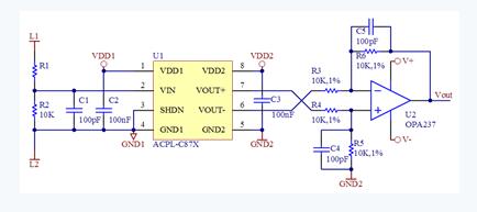
Figure 6 This circuit provides high voltage measurement and can be converted to an independent ground reference output.
Using the ACPL-C87X to isolate the voltage sensor is fairly straightforward. See Figure 6 for the DC voltage sensing circuit with ACPL-C87X. Assuming that the ACPL-C87X rated input voltage of VIN is 2V, the user needs to select resistor R1 according to R1 = (VL1-VIN) / VIN × R2. For example, if VL1 is 600 V and R2 is 10 kΩ, the value of R1 is 2990 kΩ.
Several resistors can be combined to match the target value. For example, a 2MΩ, 430kΩ, and 560kΩ resistor is connected in series with a resistance equal to 2,990 kohms. The reduced input voltage is first filtered by the anti-aliasing filter formed by R2 and C1 and then detected by the ACPL-C87X. The isolated differential output voltage (VOUT + - VOUT-) is converted to a single-ended signal (VOUT) via a post amplifier (U2). VOUT is linearly proportional to the line voltage on the high side and can be safely connected to the system microcontroller. The typical gain value of the ACPL-C87X is 1, and the total transfer function is VOUT = VL1/(R1?R2+1).
Using an isolation amplifier to detect current is also simple. Simply connect the shunt resistor to the input and then take the differential output through the isolation barrier (Figure 7). By using a suitable shunt resistor, currents of varying sizes - from less than 1A to over 100A - can be measured.
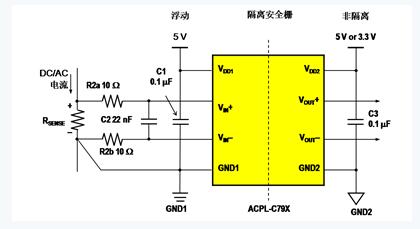
Figure 7 Measurements from less than 1A to 100A+ using a suitable shunt resistor
During operation, current flows through the shunt resistor, and the resulting analog voltage drop signal is detected by the ACPL-C79X, and the differential output voltage is formed at the other end of the optical isolation barrier. The differential output voltage is proportional to the current amplitude and can be converted to a single-ended signal by an operational amplifier, such as the post-amplifier in Figure 6, or directly to the analog-to-digital converter (ADC) that comes with the controller.
The advanced control scheme for digital communications is necessary to implement a charging control protocol between the charging station and the electric vehicle. This is another area where different standards are likely to arise. For example, SAE J1772 details the use of duty cycle modulation to control pilot signal communication for AC Levels 1 and 2. For digital communications required for DC charging, the SAE committee is updating J2931 to propose a power line communication (PLC) program for controlling pilot signals or mains. Tesla participated in the work of the SAE committee and decided to use the same signal control scheme as SAE J1772.
The most popular charging standard, CHAdeMO (based on the sales of fast-charged electric vehicles), selects the Controller Area Network (CAN) for fast charging. According to the website of the Japan Association, since the DC fast charger input reaches 500-V / 100-A, if there is an error, it may cause a fatal accident. For this reason, high reliability of communication is required. The association believes that CAN has been a highly reliable record for a long time as the standard means of communication for automotive electronic control systems. According to reports, as a communication method used by an electronic control unit (ECU) to control the charging process, the noise tolerance exceeds the PLC method ("Frequently Asked Questions - Technology").
The CHAdeMO standard provides a pair of CAN buses to connect the charger and vehicle on the coupler interface. Coupler pins 8 and 9 are named CAN-H and CAN-L, respectively ("Technical Details" [Note 13]), allowing CAN transceivers to be connected.
Adding optical isolation between the CAN transceiver and the CAN controller can significantly improve system security because the optocoupler provides a barrier that prevents any damage from being cascaded to the system MCU. This configuration improves the reliability of data communication in extremely noisy environments, such as high-voltage battery charging systems. Figure 8 shows how an optocoupler can be used to design an isolated CAN bus digital communication solution for a fast charging station. Similar circuits are also available for in-vehicle systems.
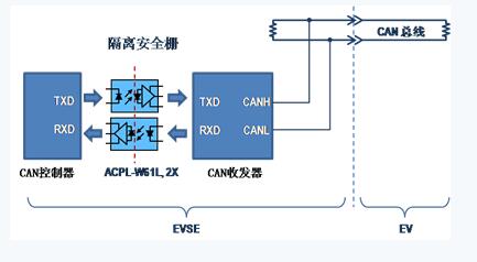
Figure 8 This setup provides isolated CAN bus digital communication for fast charging station design
In Figure 8, a pair of 10-MBd fast optical couplers (partial ACPL-W61L) are used to transmit and receive data. This product requires only 1.6 mA of LED current, and its SSO-6 package is less than half the size of a traditional DIP-8 package. According to the UL1577 standard, the ACPL-W61L can withstand a high voltage of 5000VRMS per minute. This part is designed according to a standard that can transmit signals in high transient noise with a common mode transient immunity (CMTI) of 35 kV/μs [30]. In order to adapt to different data transmission speeds, other optocouplers can be used instead of ACPL-W61L. This includes the 5-MBd level ACPL-W21L and the 25-MBb dual channel bidirectional ACSL-7210.
Conclusion While exploring the use of relatively inexpensive power sources, electric vehicles will ultimately help reduce the dependence of the global transportation industry on oil. They will also help reduce greenhouse gas and other pollutant emissions and will be further improved as more renewable energy is introduced into the power generation portfolio.
Electric vehicle charging infrastructure is a key factor driving the widespread adoption of electric vehicles worldwide. In an electric vehicle charging station, especially for DC fast charging, a complex power system is used in a short time to provide sufficient power for the battery. Safety isolation is necessary because low voltage control systems, high voltage power systems, and user-accessible user interfaces are all stored in a single charging station.
Another key design consideration for electric car chargers is power conversion efficiency. Optocouplers, such as gate drivers, voltage/current sensors, and digital communication optocouplers, provide safe isolation and electrical functionality in a single package, leading the way toward high efficiency toward the system.
DO-27 diode, DO27 Rectifier Diode
Changzhou Changyuan Electronic Co., Ltd. , https://www.changyuanelectronic.com
