First, the three-phase asynchronous motor step-down start control
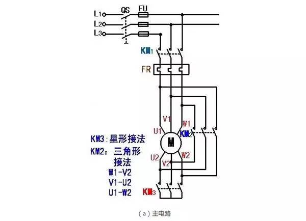
1. Y-â–³ step-down starting control of three-phase asynchronous motor
3. The relay contactor control of Y - â–³ stepping down of three phase asynchronous motor is transformed into PLC control system.
(1) Determine the external wiring diagram of the I/O signal and drawing PLC
(a) Main circuit
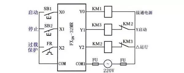
(b) PLC I/O wiring diagram
Motor Y-Δ step-down startup wiring diagram
(2) Design Y-â–³ step-down start-up ladder diagram for three-phase asynchronous motor
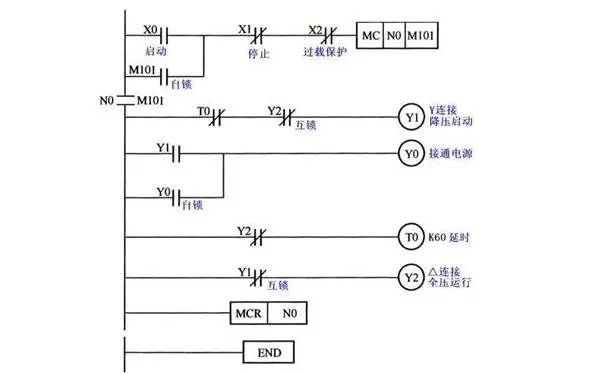
Ladder Diagram of Y-Δ Buck Start Control of Motor
2. Step-down control of series auto-transformer of three-phase asynchronous motor
Stepping down the relay contactor control of series autotransformer step-down transformation to PLC control system:
(1) Determine the external wiring diagram of the I/O signal and drawing PLC
PLC input signal: start button SB1, stop button SB2, thermal relay normally open contact FR.
PLC output signal: running contactor KM2, series connected autotransformer contactor KM1.
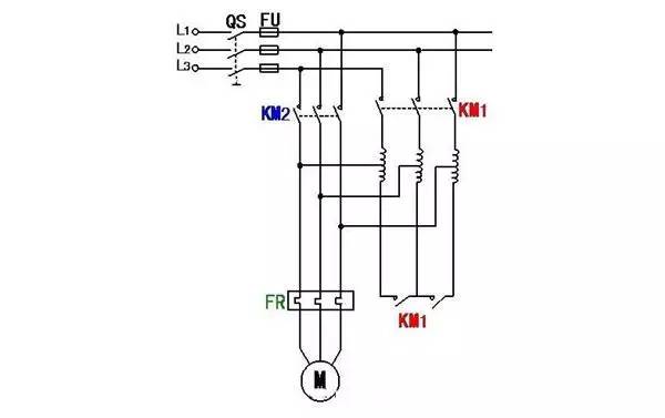
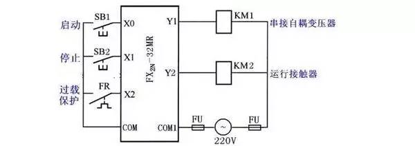
(a) Main circuit
(b) PLC I/O wiring diagram
Motor auto-transformer step-down startup wiring diagram
(2) Design step-up ladder diagram of series auto-transformer of three-phase asynchronous motor
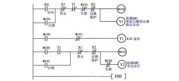
Series auto-transformer step-down start control ladder diagram for three-phase asynchronous motor
Second, the control of the three-phase winding asynchronous motor
1. Three-phase wound asynchronous motor series resistance start control
The control circuit of the relay contactor started by the string resistance of the wound asynchronous motor is transformed into a PLC control system:
(1) Determine the external wiring diagram of the I/O signal and drawing PLC
PLC input signal: start button SB1, stop button SB2, thermal relay normally open contact FR.
PLC output signal: power contactor KM, shorted R1 contactor KM1, shorted R2 contactor KM
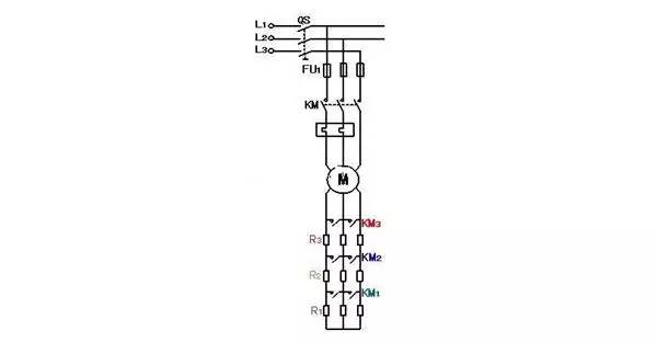
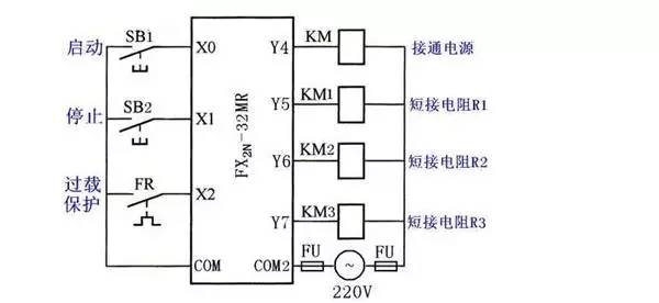
(a) Main circuit
(b) PLC I/O wiring diagram
Wiring diagram of series resistance starting of three-phase wound asynchronous motor
2. Three-phase wound asynchronous motor series frequency sensitive varistor starting circuit
The control circuit of the relay contactor activated by the string-type asynchronous motor serial-frequency sensitive rheostat was transformed into a PLC control system:
(1) Determine the external wiring diagram of the I/O signal and drawing PLC
PLC input signal: start button SB1, stop button SB2, thermal relay normally open contact FR.
PLC output signals: run contactor KM1, short-circuit frequency-sensitive varistor contactor KM2, relay relay relay KA connected to the thermal relay.
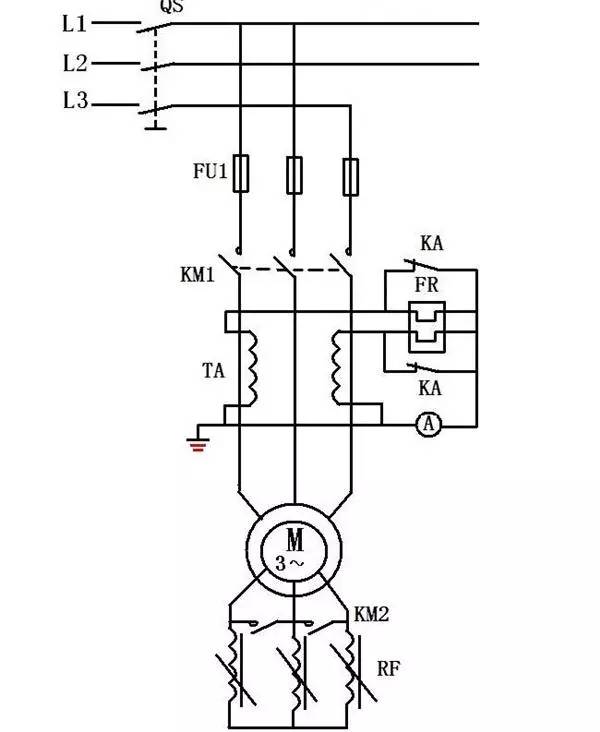
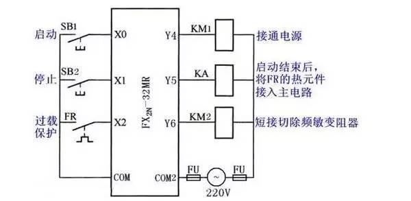
(a) Main circuit
(b) PLC I/O wiring diagram
(2) Start-up ladder diagram for designing three-phase wound asynchronous motor series-frequency sensitive rheostat
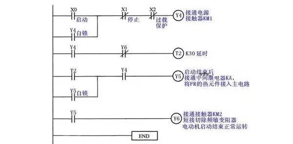
Start-up Ladder Diagram of Three-phase Wound-string Asynchronous Motors Series Frequency Sensitive Rheostat
Third, automatic round-trip control
Transform the control circuit of relay contactor that is controlled automatically and back into PLC control system:
(1) Determine the external wiring diagram of the I/O signal and drawing PLC
PLC input signal: forward start button SB1, reverse start button SB2, stop button SB3, thermal relay normally open contact FR, forward forward limit switch SQ1, reverse backward limit switch SQ2, forward limit switch SQ3, back limit limit switch SQ4.
PLC output signal: positive running contactor KM1, reverse running contactor KM2.
Automatic round trip control diagram
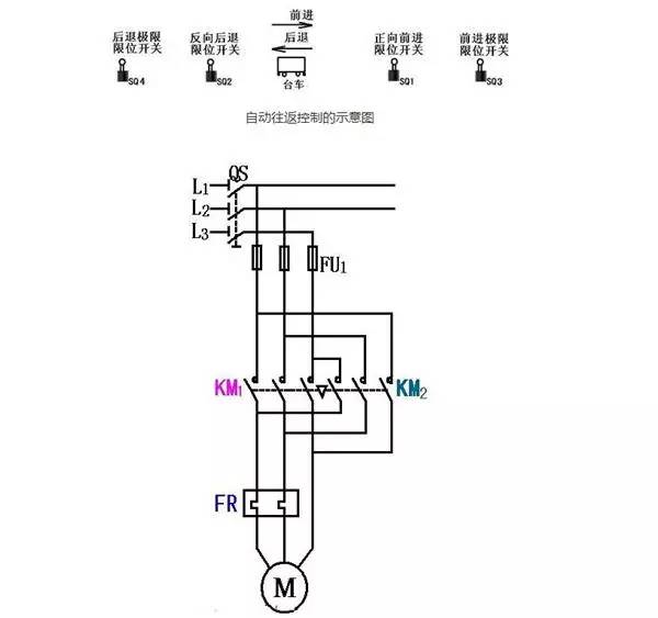
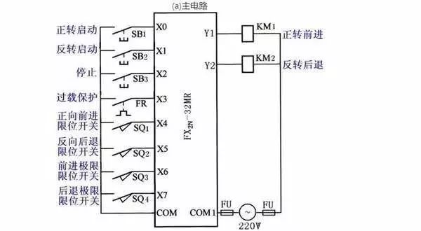
(a) Main circuit
(b) PLC I/O wiring diagram
Automatic return control wiring diagram
(2) Design ladder diagram
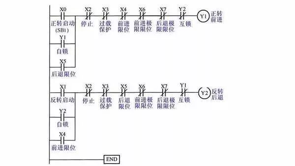
Automatic relay control ladder diagram
IV. Ladder diagram empirical design method
(A) The characteristics of ladder diagram of PLC control system
(1) Input signal and output load of PLC control system: The AC contactor and solenoid valve actuators in the relay circuit diagram are controlled by the PLC output relays, and their coils are connected to the PLC output terminals. Buttons, control switches, limit switches, proximity switches, etc. are used to provide PLC with control commands and feedback signals. Their contacts are connected to the input of the PLC.
(2) The functions of the intermediate relays and time relays in the relay circuit diagram are performed using the PLC's internal auxiliary relays and timers. They are independent of the PLC's input relays and output relays.
(3) Set the middle unit: In the ladder diagram, if multiple coils are controlled by a certain contact series and parallel circuit, an auxiliary relay controlled by the circuit may be set in the ladder diagram to simplify the circuit. The auxiliary relay is similar to Intermediate relay in relay circuit.
(4) Time Relay Instantaneous Contact Handling: In addition to the time-delayed contacts, the time relay also has a momentary contact that acts when the coil is energized or de-energized. For a time relay with a momentary contact, an auxiliary relay can be connected in parallel across the corresponding coil of the timer in the ladder diagram. The contact of the latter corresponds to the momentary contact of the time relay.
(5) Processing of the power relay delay relay. FX series PLCs do not have timers with the same function, but they can use the delayed timer after the coil is energized to achieve the power-off delay function.
(6) Establishment of an external interlock circuit. In order to prevent the two contactors that control the positive and negative rotations from operating at the same time, causing a short-circuit in the three-phase power supply, in addition to the soft interlock circuit formed by the normally closed contacts in series with the coils of the output relays corresponding to their corresponding output relays in the ladder diagram, Set the hard interlock circuit outside the PLC.
(7) Thermal relay overload signal processing: If the thermal relay belongs to the automatic reset type, the overload signal must be provided to the PLC through the input circuit, and the overload protection is implemented using a ladder diagram. If it is a manual reset type thermal relay, its normally closed contact can be connected in the output circuit of the PLC in series with the coil of the AC contactor that controls the motor.
(8) Rated voltage of external load: PLC's relay output module and bi-directional thyristor output module can only drive the rated voltage of AC 220V. If the coil voltage of the original AC contactor of the system is 380V, the coil should be replaced with 220V, or set the relay outside the PLC.
(B) Experience Design Method
The method used in the above example programming is "empirical design method." As the name implies, "empirical law" is a method of designing based on the designer's experience.
1. The point of experience design method
(1) PLC programming, from the perspective of the ladder diagram, its fundamental point is to find out the working conditions of each output of the system that meets the control requirements. These conditions are always implemented by using a variety of internal devices in a certain logical relationship.
(2) The basic mode of the ladder diagram is the start-stop-stop circuit. Each of the start-stop-stop circuits is generally only for one output. This output can be the actual output of the system, or it can be an intermediate variable.
(3) There are some basic steps in ladder programming, they all have certain functions and can be applied in many places like swing blocks.
2. "empirical method" programming steps
(1) After an accurate understanding of the control requirements, input and output ports are reasonably assigned to events in the control system. Select the necessary internal devices such as timers, counters, and auxiliary relays.
(2) For some simpler control output requirements, their operating conditions can be directly written out and the related ladder diagram branches can be completed according to the Kai-pause-stop circuit mode. Working conditions are slightly more complex with auxiliary relays.
(3) For more complex control requirements, in order to draw the ladder diagram of each output port with the start-stop-stop circuit mode, it is necessary to correctly analyze the control requirements and determine the key points that make up the total control requirements.
(4) Express key points in ladder diagrams. The key points are always expressed by the internal devices. Reasonable arrangements need to be made when arranging internal devices. When you draw a ladder diagram of a key point, you can use common basic links, such as timer timing, oscillation, and so on.
(5) On the basis of completing the key-point ladder diagrams, the ladder diagrams are drawn for the final output of the system. Use key points to synthesize the final output control requirements.
(6) Examine the above drafting paper, and on this basis, add missing features, correct mistakes, and make final improvements.
36V Bms,Bms For E-Bike,Bms For Scooter,10S 36V 15A Bms
HuiZhou Superpower Technology Co.,Ltd. , https://www.spchargers.com
