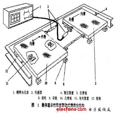
This system is mainly used for the detection of the amount of side slip of automobile wheels. In order to ensure the straight rolling of the steering wheel of the car without lateral slip, it is required that the camber angle of the wheel and the toe of the wheel be properly matched. When the value of the toe of the wheel and the camber of the wheel are not properly matched, the wheel may not roll purely during straight travel. The side slip phenomenon occurs. When this slippage phenomenon is too severe, it will destroy the attachment conditions of the wheels, lose the ability to orientate, cause traffic accidents and cause abnormal wear of the tires. The magnitude and direction of the amount of lateral slip can be detected with a vehicle wheel slip test stand.
Structure of side sliding table:

System hardware configuration:
2 displacement sensors
2 groups of photoelectric switches
Analog input module
Switch input module
Working principle of the system:
When the wheels step on the side slide, the first group of photoelectric switches are turned off (the photoelectric switch is normally open when not blocked), and when leaving the side slide, the second group of photoelectric switches are turned off, and the side slip of the wheel is recorded at this time. The test of a group of wheels is completed. The wheels step on the side skateboards in sequence and record the amount of side slip as described above to complete the side slip test of the entire vehicle.
System functions:
Automobile positioning: The system provides three different automobile positioning systems, which are single-axle positioning, double-axle positioning and multi-axle positioning. Among them, multi-axle positioning needs to detect the amount of side slip of 6 groups of wheels.
System settings: You can set the upper and lower limit alarm values ​​for the amount of side slip, the length of the skateboard, and the current trademark of the vehicle under test.
Customer management: able to record and modify information of detected vehicles and support printing.
Structure and working principle:
1. The main structural type of pressure relief valve is external spring type, with or without directional guiding device. Its main components are composed of spring, valve seat, spring seat, valve housing (cover), marker rod, signal switch (occurrence box), sealing ring and other parts.
2. Working principle
When an accident occurs inside the oil immersed transformer, the oil in the oil tank is vaporized, generating a large amount of gas, which makes the internal pressure of the oil tank rise sharply. If the pressure is not released in time, the fuel tank will be deformed or burst. The installation of the pressure relief valve means that when the pressure in the oil tank rises to the opening pressure of the pressure relief valve, the pressure relief valve opens rapidly within 2ms, making the pressure in the oil tank drop quickly. When the pressure drops to the closing pressure value of the pressure relief valve, the pressure relief valve is closed reliably, so that the positive pressure in the oil tank is always maintained, effectively preventing external air, moisture and other impurities from entering the oil tank; When the pressure relief valve is opened, the marker rod is in the direction of. The upper action and obvious extension of the top cover indicate that the pressure relief valve has been operated. When the pressure relief valve is closed, the marker rod remains at the position after opening, and then it can only be reset manually. Compared with the safety airway, it has the advantages of accurate and reliable movement, no damage to parts after movement, and no replacement.
purpose
â— The product has electrical alarm signal, which can realize remote monitoring.
â— Applicable to liquid or gas insulated transformers, transformers, on load tap changers, high-voltage switches and other electrical products.
â— In case of internal failure of electrical equipment, the valve will open to release the pressure in the oil tank to avoid deformation and bursting of the oil tank.
â— When the pressure in the oil tank drops to the closing pressure of the valve, the valve will be closed again to prevent external moisture and impurities from entering the tank.
◠Ambient temperature: - 30 ℃~40 ℃.
â— Installation position:
a) Installed on the fuel tank cap;
b) On the upper side wall of the oil tank;
c) Raise the seat.
Pressure Relief Valve,Gas Relief Valve,Gas Relief Safety Valve,Electric Contact Pressure Valve
Henan New Electric Power Co.,Ltd. , https://www.newelectricpower.com
