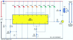
Here, it is easy to make a circuit diagram of the battery level indicator. In general, on the phone, the battery level shows the point or bar style. This can help you recognize the battery level effortlessly. On this page, we provide a circuit that can help you recognize the battery level of the instrument and is the number of LEDs that are illuminated. It works for all 10 LEDs. So, if there are 3 LED lights, it symbolizes 30% of the battery power. The battery level indicator function in the phone is integrated with other functions in this circuit, the difference is just a single comparator IC (LM3914) all of this.
The LM3914 uses a 10 comparison and is built according to the current division of labor rules. Therefore, it is divided into 10 battery levels.
The circuit gets the power source of the battery from the operation of the instrument itself. It uses 10 LEDs connected in a 10-point mode. Applying LEDs of various colors helps it simplier, making it easier to judge based on the calibration voltage levels made. The red LED (LED1 through LED3) shows that the battery is below 40%. The orange light-emitting diode (LED4 through LED6) 40 indicates that the battery level is below 70%, and the green indicator light (LED7 through LED10) shows 70% of the battery power to less than 100%. The brightness of the LED can be fine-tuned by changing the value of the variable resistor VR2 between pins 6 and 7.
Diode D1 prevents the reverse polarity of the battery from connecting to the circuit. The tenth LED illuminates only when the battery is fully charged, ie, the battery is fully charged. When the battery is fully charged, the relay drives transistor T1 to perform relay RL1. This will stop charging (one N / O) normally open contact relay RL1 mode.
Calibrated, connected to a 15V adjustable, regulated power supply, and set at 3V for the first time. Gradually change VR1 until the final LED1 illuminates. Now, increase the input voltage to 15V at the correct step of 1.2V until the corresponding LED (LED2 through LED10) is lit.
Now ready to display any voltage value maximum voltage circuit. Since the number of LEDs is 10, we can simply give up considering that the maximum voltage of a single LED is 10%.
Connect the battery voltage from any input probe tested in the circuit. Looking at the total number of LEDs that shine, you can easily know the level of your battery. Assume that 5 LEDs are illuminated. In this case, the power battery is 50% to 59% of its maximum value.
Establish a universal PCB simpe battery level indicator circuit. After calibration, attach the inside. Make 10 LEDs, if necessary with variable resistance battery input and 2 hole holes.
Temperature Controlling Thermostat,Thermal Cutout Water Heater,Thermal Cut Out,Limit Thermostat Cutout
Foshan City Jiulong Machine Co., Ltd , https://www.jlthermostat.com
