The monitoring system uses the LPC2292 embedded microprocessor in the ARM7 series chip, which is mainly used to measure the physiological parameters of the human body, such as: electrocardiogram, blood pressure, blood oxygen saturation, body temperature and so on. Because the system needs to collect and process a large amount of data information, it is difficult or even impossible to process these data information with single-task software on the CPU. Therefore, the μC / OS-Ⅱ operating system that can handle multi-tasks is selected in the design. It provides a safe and reliable operating system platform and shortens the development cycle.
2 System hardware design
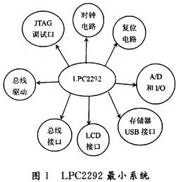
ARM 7 series chip LPC2292 minimum system is shown in Figure 1:

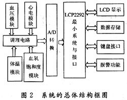
The overall block diagram of the system is shown in Figure 2.
It can be seen from Figure 2 that the entire system takes the ARM 7 series chip LPC2292 as the core, and expands some peripheral circuits on its periphery, so as to realize the safety inspection of human physiological parameters: electrocardiogram, blood pressure, blood oxygen saturation, and body temperature. The system collects the physiological parameters of the human body through the ECG module, blood pressure module, blood oxygen saturation module, and body temperature module, and filters and amplifies these signals by the conditioning circuit. The LPC2292's own A / D converter converts the transmitted analog signal into Digital signals, and finally the parameters of the human body are displayed on the LCD.

2.1 ARM system module
The ARM system is the control center of this system. It mainly completes operations such as calculation, control, and management, and is the core module of the system. The system uses the ARM 7 series chip LPC2292, which is based on a 16 / 32-bit CPU that supports real-time simulation and tracking, and has a 256 kb embedded high-speed FLASH memory. The 128-bit wide memory interface and unique acceleration structure enable 2-bit code to run at the maximum clock rate. Applications with strict code size control can use the 16-bit Thumb mode to reduce the code size by more than 30%, but the performance loss is very small. The LPC2292's 144-pin package, extremely low power consumption, multiple 32-bit timers, 8 10-bit ADCs, 2 PWM channels, and up to 9 external interrupts make them particularly suitable for medical system, automotive, and industrial control applications And fault-tolerant maintenance bus.
2.2 LCD display module
The LCD display module mainly completes functions such as data display, output data synchronization and display data. Since there is no function module of the liquid crystal controller in the LPC2292, if the selected liquid crystal screen does not have a liquid crystal controller, then, to enable the CPU to control the liquid crystal, a liquid crystal drive control circuit must be added. Therefore, the LCD screen HLM6323 with its own controller is selected in this system. He is a 5-inch pseudo-color LCD screen, the pixels are 320 × 240 dot matrix, each point requires RGB three-color data, each color requires 1 byte of data. The design requirements require continuous viewing of the image, and 25 frames per second according to the standard, then at least 25 × 8 × 320 × 240 = 15 360 000 bits of data must be transmitted per second. If serial transmission is used, 4.6 Mb / s serial transmission speed, but unfortunately, no serial standard transmission is greater than this speed, therefore, it is necessary to choose parallel data transmission.
2.3 Alarm module
When the measured physiological parameters, such as electrocardiogram, blood pressure, blood oxygen saturation, and body temperature exceed the preset normal values, an alarm is generated to remind patients to promptly perform treatment or medical staff to take rescue measures.
2.4 FLASH data storage and USB interface
This module is designed to ensure the preservation and extraction of real-time data. In this system, NAND08GW3D2 series memory chips are selected. Because the pins of the device with different storage density are the same, the system can be upgraded to a high-capacity storage device without changing the circuit. A USB device interface is extended through the USB device interface chip ISP1161A1. Through the USB interface, the data recorded by the monitoring system can be uploaded to the PC, and the PC can also download the program to the memory of the LPC2292 processor through the interface.
2.5 System power
Power supply design is a key part of a system design. For the entire system, a stable power supply with a certain power and reasonable power management are essential. The system has the following power supplies: CPU core digital and analog power supply voltage +1.8 V, CPU I / O port digital and analog power supply voltage +3.3 V, bus isolated power supply, LCD drive power supply, LCD backlight inverter Power supply, other peripheral equipment power supply voltage +5 V and other power supplies.
3 Software design
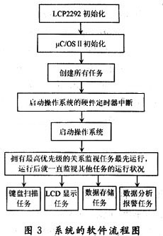
The software design of this system mainly includes the development of ARM application program and the transplantation of μC / OS-Ⅱ operating system. ARM's application programs mainly include LCD display programs, FLASH storage programs, USB communication programs, keyboard scanning programs, A / D programs, and alarm programs. The μC / OS-Ⅱ operating system is to coordinate the task management and scheduling of the program by LPC2292. The software flow chart of the entire system is shown in Figure 3.

3.1 Design idea of ​​LCD driver software
The function of the LCD driver software is to complete the final output and display of data. Its main software processes include data sending and receiving, key reading on the LCD, and LCD scanning. Data transmission and reception is to complete the data transmission between the CPU and the LCD liquid crystal display. The CPU sends data to the LCD through the driver chip, and the LCD returns response data to the CPU. In order to enhance the readability of the human-machine interface, several buttons are set on the LCD. When there is a button response, a corresponding response should be sent to the CPU, and the display interface of the LCD and other system parameters can be set through the buttons . The scanning of the LCD is to ensure that there is no obvious interruption of the display, and that there is no flower screen phenomenon, and an accurate error response can be performed when the flower screen phenomenon occurs. The key design does not use hardware interrupts for each key, because in this system, the task priority of the LCD display driver is the highest in the application program. The keys use a hardware external interrupt, and then use software to interrupt the keys. Arrange and determine the software priority; another reason is that there are not enough hardware interrupts to be set as key interrupts due to the large number of buttons. If it is set to interrupt expansion, in addition to hardware expansion, software expansion will also waste a lot of resources.
In this design, the LCD driver needs to write 2 files, one of which is a C language file and the other is a C language header file. The C language file is a communication interface protocol file and needs to exchange data with other modules. The header file is to design some basic parameters of the LCD. During the operation of the system, these parameters are basically unchanged.
3.2 Design idea of ​​USB communication software
The USB communication software designed by this system is implemented by interrupt response. The purpose of this is that the CPU can do other work when there is no USB device or no USB device, saving the resources of CPU and operating system. It is beneficial to protect the CPU.
3.3 Design idea of ​​FLASH read-write operation software
The entire program file includes several parts such as chip erasing, chip writing and reading, and data verification. Erase is for the memory to be reused without replacing the chip; the chip writing and reading is the center of the entire file, responsible for writing the data of the memory, and reading the data at the appropriate time; the verification is to ensure the correctness of the data , An alarm is required when an error occurs.
In this design, the memory has three memory address entries, and all data needs to pass through these three address entries. Therefore, it must be ensured that the three address entries do not cross the address with other addresses at any time.
3.4 transplantation of μC / OS-Ⅱ operating system
The μC / OS-Ⅱ real-time operating system is a portable, curable, tailorable and strippable multi-task real-time kernel (RTOS), suitable for various microprocessors and microcontrollers. Its performance is comparable to various commercial cores, and it performs better in some respects. All codes are written in ANSI C language, so it has good portability.
Unlike other real-time operating systems, μC / OS-Ⅱ provides users with a standard API function. Program developers use the API functions provided by the operating system to develop application programs. To develop application programs on the μC / OS-Ⅱ kernel, program developers need to build their own real-time operating systems based on the real-time kernel. First, transplant μC / OS-Ⅱ to its own hardware target board, write the corresponding driver program and user graphical interface, etc .; on top of these interface functions, plus the user's own application program, constitute the embedded software .
The transplantation conditions of μC / OS-Ⅱ are: the processor C compiler can generate reentrant code; the processor supports interrupts and can generate timed interrupts; the C language can turn on and off interrupts; the processor supports a certain amount of data Store the hardware stack; the processor has five requirements for the instructions to read the stack pointer and other CPU registers and save them to the stack or memory. Philips LPC2292 chip and ADS1.2 C compiler together can meet the above five conditions, so this design is completely portable operating system to improve the system's functionality.
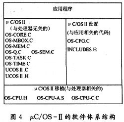
The architecture of μC / OS-Ⅱ software is shown in Figure 4:

Although most of the source code of μC / OS-Ⅱ is written in C language, it must be implemented in assembly language when completing some codes related to the processor. The reading and writing of registers can only be achieved through the storage and loading instructions of assembly language.
Transplanting μC / OS-Ⅱ to a new architecture requires modification of the following three files:
(1) C language header file OS-CPU.H;
(2) C language source file OS-CPU.C;
(3) Assemble the source file program OS-CPU-A.ASM.
The human physiological parameter monitoring system is implemented on the hardware platform based on the ARM7 microprocessor, using the current popular μC / OS-Ⅱ real-time multitasking operating system, which can detect the user's ECG, blood pressure, blood oxygen saturation and body temperature in real time. And can carry on the data analysis to it, when there is abnormality, it can automatically alarm so that the user can be treated in time. The system has high scalability, and can be directly expanded on the system according to the needs, so that it has a remote human physiological parameter monitor with GPS, GPRS, and CDMA functions.
Enershare's commitment to future-ready energy solutions for smart home innovations, Enershare`s Energy Storage Systems create a flexible energy maintenance system for homeowners who want to take more control of their home energy use, it is intended to be used for Home Battery energy storage and stores electricity for solar self-consumption, load shifting, backup power, and off-the-grid use. you can use it anytime you want-at night or during an outage.
Home Battery,Home Battery Backup,Home Energy Storage System,Battery Backup Power Supply For Home,High Capacity Electrical Backup,Power Bank For Home
Shenzhen Enershare Technology Co.,Ltd , https://www.enersharepower.com
