Abstract: MAX4007 is a high-precision, high-side, high-voltage current monitor designed to monitor the current of photodiodes in fiber optic systems. This application note describes an easy way to increase the response time of the MAX4007 in GPON burst mode operation.
Working Principle The MAX4007 is a current monitor. The output current is proportional to the current flowing out of the REF pin. If an ADC is used to sample the output, the output must be converted to a voltage signal. A simple method is to use the output resistance in parallel with a 10nF anti-aliasing capacitor. This way (Figure 1) can be found in the device data sheet.
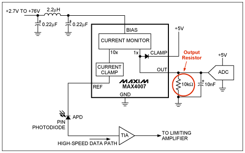
Figure 1. MAX4007 application example
In this configuration, the output load of the current monitor is a resistor, regardless of the presence or absence of anti-aliasing capacitance, it will cause a slow response. An easy way to overcome this limitation is to use an output transimpedance amplifier instead of the output resistor. This change eliminates the loading effect at the output of the MAX4007 and fully increases its operating speed. This design method is very useful in GPON burst mode controllers that require response times within 100 nanoseconds.
In order to better explain the difference between the two methods, we test through the actual circuit, the circuit shown in Figure 2 is used to test the basic functions of the MAX4007.
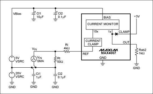
Figure 2. This circuit tests the operating speed of the MAX4007
Figure 2 is a circuit example for testing the MAX4007 high-voltage application (such as required by APD), which can also be used for PIN photodiodes or other low-voltage photodetectors. The input circuit is composed of VIN, Rt and Ri, used to simulate the switching current element, similar to the role of the photodiode. Because VIN is generated by a function generator with a maximum voltage swing of ± 5V, the 20V supply voltage is used as a reference for the function generator signal, so the circuit can be tested with a 25V bias. Ci1, Ci2, Cf1, Cl1 and Cl2 provide filtering and will not affect the normal operation of the circuit. Selecting components and VIN produces a step current of 1mA to 10µA. Figure 3 shows the circuit response in this configuration.
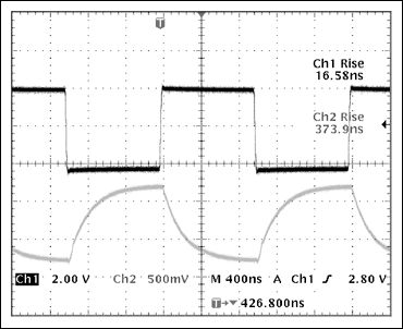
Figure 3. The data shows the response of the MAX4007 when using a resistor as the output device.
The curve shown in Figure 3 is similar to the response given by the device data sheet.
If you replace the passive output device in the circuit, you can greatly improve the response time of the MAX4007, as shown in Figure 4.
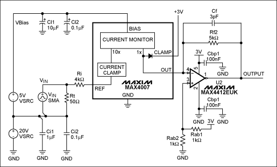
Figure 4. The MAX4007 works with an output operational amplifier
Figure 5 shows the MAX4007's large signal pulse response when a 10µA to 1mA step current is applied to the REF pin. The pulse rise time constant is approximately 57ns and the fall time constant is approximately 26ns.
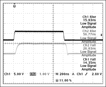
Figure 5. MAX4007 response when using an output op amp
The application circuit shown in Figure 4 is very compact, requiring only a SOT23 device (MAX4007), an SC70 packaged op amp (MAX4412), and a small number of discrete components.
Working Principle The MAX4007 is a current monitor. The output current is proportional to the current flowing out of the REF pin. If an ADC is used to sample the output, the output must be converted to a voltage signal. A simple method is to use the output resistance in parallel with a 10nF anti-aliasing capacitor. This way (Figure 1) can be found in the device data sheet.

Figure 1. MAX4007 application example
In this configuration, the output load of the current monitor is a resistor, regardless of the presence or absence of anti-aliasing capacitance, it will cause a slow response. An easy way to overcome this limitation is to use an output transimpedance amplifier instead of the output resistor. This change eliminates the loading effect at the output of the MAX4007 and fully increases its operating speed. This design method is very useful in GPON burst mode controllers that require response times within 100 nanoseconds.
In order to better explain the difference between the two methods, we test through the actual circuit, the circuit shown in Figure 2 is used to test the basic functions of the MAX4007.

Figure 2. This circuit tests the operating speed of the MAX4007
Figure 2 is a circuit example for testing the MAX4007 high-voltage application (such as required by APD), which can also be used for PIN photodiodes or other low-voltage photodetectors. The input circuit is composed of VIN, Rt and Ri, used to simulate the switching current element, similar to the role of the photodiode. Because VIN is generated by a function generator with a maximum voltage swing of ± 5V, the 20V supply voltage is used as a reference for the function generator signal, so the circuit can be tested with a 25V bias. Ci1, Ci2, Cf1, Cl1 and Cl2 provide filtering and will not affect the normal operation of the circuit. Selecting components and VIN produces a step current of 1mA to 10µA. Figure 3 shows the circuit response in this configuration.

Figure 3. The data shows the response of the MAX4007 when using a resistor as the output device.
The curve shown in Figure 3 is similar to the response given by the device data sheet.
If you replace the passive output device in the circuit, you can greatly improve the response time of the MAX4007, as shown in Figure 4.

Figure 4. The MAX4007 works with an output operational amplifier
Figure 5 shows the MAX4007's large signal pulse response when a 10µA to 1mA step current is applied to the REF pin. The pulse rise time constant is approximately 57ns and the fall time constant is approximately 26ns.

Figure 5. MAX4007 response when using an output op amp
The application circuit shown in Figure 4 is very compact, requiring only a SOT23 device (MAX4007), an SC70 packaged op amp (MAX4412), and a small number of discrete components.
Specialed in developing and manufacturing in all kins of mobile phone chargers around 15 years with our own brand MLF, also with much OEM/ODM experience and including help our customer to do customized plastic housing mold . Our factory can output 300K pcs high quality USB 2.0 Mobile Phone Charger daily
Mobile Phone Charger
Mobile Phone Charger,Fast Phone Charger,Cell Phone Charger,Dual Usb Charger
Meile Group Limited , https://www.hkmeile.com
