The use of GPS (Global Positioning System) for positioning and navigation is the most basic application of GPS. With the expansion of urban construction in China and the increasing number of vehicles, the management and rational dispatch of transportation has become a widespread concern, especially the world. After the positioning system (GPS) is changed from military to civilian, the application of GPS technology to the monitoring of mobile targets has advantages that other monitoring methods cannot match. Therefore, it is a new research hotspot to implement monitoring and scheduling management for various vehicles by using GPS technology.
This article refers to the address: http://
The overall structure and working principle of the system
The GSM-based GPS vehicle positioning monitoring system is an ideal solution for vehicle management. The system uses GPS technology to locate mobile targets in real time, and uses GSM digital mobile communication network for real-time data transmission. With electronic map and spatial information system as support platform, it realizes location tracking, monitoring alarm, anti-robbery, command and dispatch and information inquiry. management. The whole system is composed of two parts: GPS satellite positioning system and ground mobile communication system. The ground mobile communication system is composed of command and control center, vehicle mobile unit and GSM.
The communication network consists of three parts. The vehicle mobile unit device can provide the latest positioning data, operating status and alarm information of each mobile target in real time for the command monitoring center, and automatically record the information for later inquiry and analysis, which is a user terminal. The Command and Control Center combines the GIS (Geographic Information System) electronic map to display the geographical location of the currently monitored and commanded vehicles in real time. The GSM communication network transmits data, voice and images.
System monitoring center
The structure of the system monitoring center is shown in Figure 1. It mainly includes GSM communication network, GIS terminal, electronic display, monitoring terminal and main control computer. The monitoring center receives the GPS positioning data information transmitted by the vehicle mobile unit, and processes the alarm and scheduling information of the vehicle. The GIS map matching can display the current precise position of the vehicle on the electronic map in real time, thereby conveniently implementing the vehicle. Scheduling, monitoring, commanding and other functions; at the same time, various control commands can be sent to the designated vehicle station through the GSM wireless communication network to realize remote control and information inquiry service for the vehicle.
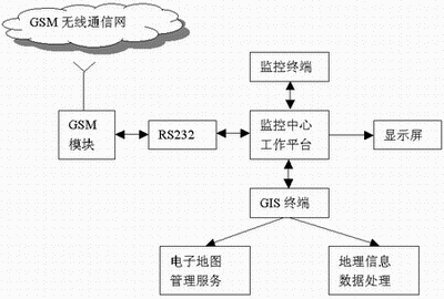
Figure 1 GPS vehicle monitoring and command system center structure
Design of the main components of the vehicle mobile unit
The vehicle mobile unit is composed of a main controller CPU, a GPS receiver, a GSM wireless communication module, a function control unit (handle) and a liquid crystal display, and its structural principle is shown in FIG. 2 .
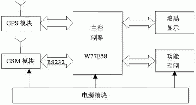
Figure 2 Schematic diagram of the hardware structure of the vehicle mobile unit
The vehicle mobile unit receives the positioning signal transmitted by the GPS satellite through the GPS receiving antenna, and calculates the positioning data such as the date, time, latitude and longitude, speed and driving direction of the vehicle through the CPU main controller. The main controller CPU is the core, processing the positioning information sent by the receiver, displaying the positioning information and the control information sent by the monitoring center on the LCD screen, and controlling the GSM module to send and receive short messages, and the handle control unit realizes remote monitoring, Request services, Chinese short message reception and calls. Since the GSM wireless module and the GPS module are connected to the MCU by serial communication, the hardware design is relatively simple. In this design, the MCU selects Winbond's W77E58 because it has two serial ports that can simultaneously be combined with the GSM module. The GPS module communicates, and its instructions are fully compatible with the MCS-51. The chip has a 32k flash MTP ROM, a programmable watchdog timer, etc. It can save a lot of peripheral components and improve the stability of the system. The system main controller circuit is shown in Figure 3.
GSM wireless communication
There are two communication methods for the GPS vehicle positioning monitoring management system: a dedicated wireless communication network and a public GSM network. The GPS/GSM vehicle positioning monitoring management system uses the GSM short message service to realize the bidirectional transmission of data. The short message service establishes a signaling connection between the mobile station and the mobile service switching center, which has priority and high pass rate. The code rate is extremely low. This is an unmatched benefit of the private network and cluster network brought by the GSM public network. The biggest advantage of short message for vehicle monitoring is that the connection is simple, the connection is fast, and the service cost is low. This is suitable for timing to send the positioning information to the monitoring center.
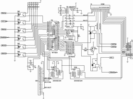
Figure 3 system main controller circuit
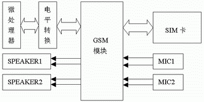
Figure 4 WM01-G900/1800 peripheral circuit design block diagram
.
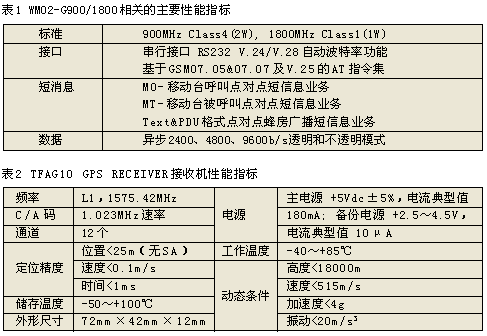
In practical applications, we use WM02-G900/1800. Its peripheral circuit design block diagram is shown in Figure 4, and its related performance indicators are shown in Table 1. It communicates with the microcontroller using a standard serial port, and the highest baud rate for communication can reach 115 200b/s. Data communication between the GSM module and the SIM card is mainly through the SIMCLK and SIMDATA signal lines. In order to ensure that the time interval between the sending of the short message and the arrival of the short message is as short as possible, the selected SIM card is preferably provided by the same telecommunications carrier. When using the GPRS function, you also need to select the SIM card that supports GPRS and open the GPRS service. The module also supports driving two microphones, two speakers and one buzzer. One of the microphones and speakers can be connected to the handset of the handle to realize the car phone function; the other channel can realize the monitoring and hands-free functions, but the two channels cannot work at the same time. If the hands-free mode is needed during the call, the AT can be used. Command: AT+SPEAKER=0 or 1 to switch.
The logic level of the I/O interface of WM02-G900/1800 is 3V. When it communicates with the serial port of the microcontroller, it needs to perform level conversion. The author chooses MAX3237/3238 for conversion in the application. If GPRS service is needed, You can also choose the TC-45 module from Siemens and the GR47 from Sony Ericsson, which support the transmission in GSM/GPRS format.
Controlling the WM02-G900/1800 module for short message transmission and voice communication is the key to the design. If it is not familiar with the relevant AT commands, it will not be properly set, which will affect the normal operation of the system and bring unpredictable results. as a result of.
GPS receiver and its data format
The GPS OEM board is used to receive signals from GPS satellites and calculate the current location of the vehicle terminal. It consists of a frequency converter, signal path, microprocessor and memory unit. The GPS module sends positioning coordinates to the main controller through the serial port; the main controller can also send a setting command to the GPS module to control the status and working mode of the GPS module. The GPS module needs to be equipped with a dedicated GPS antenna to receive GPS satellite signals. Generally, in more open areas, more than three GPS satellite signals are required to be accurately located. In the car GPS intelligent terminal system, placing the antenna on the roof can have a better positioning effect. We choose TFAG10 GPS RECEIVER. Its performance indicators are shown in Table 2.
The input and output of the TFAG10 GPS RECEIVER receiver statement are completed via the RS-232 serial interface and conform to the NMEA-0183 communication standard format developed by the National Ocean Electronics Association. The data format of its communication port should be set to 8 data bits, 1 start bit and 1 stop bit; no parity; baud rate is 4800b/s. The output data of the NMEA-0183 communication standard uses ASCII code, which contains information such as latitude, longitude, altitude, speed, date, time, heading, and satellite status. There are five kinds of statements. For different applications, the selected statement records are different. In this design, only the date and time, latitude and longitude, and ground speed are concerned. Therefore, only the RMC record statement is selected. A $GPRMC statement contains 13 records: statement identifier, world time, positioning state, latitude, latitude, longitude, longitude, ground speed, ground route, date, magnetic declination, checksum end mark, which occupy a total 70 bytes (which also includes 11 commas used to separate records), for example: $GPRMC, 161229.487, A, 3723.2475, N, 12158.3416, W, 0.13, 309.62, 120598, , *10
Power supply design
In the power supply design of in-vehicle equipment, we focus on the following issues:
◠Fully consider the fluctuations and pulse interference of the vehicle power supply, select the appropriate power filter; ◠Since the car battery has +12V and +24V, the power supply of the vehicle equipment should be designed as a wide input voltage (the input voltage range of the power module we selected is 7~35V); ◠Vehicle equipment should use low-power devices and take measures such as powering off the GPS module and GSM module when parking, to minimize the power consumption of the vehicle equipment, so as to avoid damage to the vehicle battery when the vehicle is parked for a long time. For the 50AH car battery, if the standby current of the vehicle terminal is 140mA, it can last for 357 hours for about 15 days when parking; ◠Overcurrent and overvoltage protection measures should be taken.
In this system, we use LM2596 series switching regulator integrated circuit, the main performance indicators are shown in Table 3.
The actual use proves that using LM2596 series switching regulator integrated circuit as the power module of this system can not only improve the working efficiency of the power supply, reduce the energy loss, reduce the thermal damage to the core device, but also reduce the fluctuation of the external car level voltage. The interference of the device can also reduce the pulse interference caused by the power supply, which can play a multiplier role in ensuring the safe and reliable operation of the system. The power supply circuit is shown in Figure 5.
.
How system devices work
After the equipment is installed, it will be powered on for the first time, and the vehicle equipment will start working.
After the vehicle is turned off, the user applies the remote control to turn on the anti-theft function. At this time, the anti-theft input and the door opening and closing detection function immediately until the user uses the remote control to disarm. The setting/disarming of the vehicle is confirmed by the linkage of the taillights of the vehicle and the siren. If the door is not closed when the defense is in place, it can be prompted by sound and light. Usually, the GSM module of the in-vehicle device is in a standby state. When receiving the instruction from the center, the in-vehicle device sends a short message according to the central command. Regardless of whether the vehicle is driving or parked normally, once the emergency alarm button on the vehicle is pressed, or the medical help and traffic rescue button is pressed, the in-vehicle device can automatically report the location and alarm type to the center via the mobile phone in a short message. . The anti-theft alarm sensing device connected to the in-vehicle device will automatically report the position and alarm type to the center through the GSM module immediately after the vehicle is stopped and has been armed.
The in-vehicle device can complete the corresponding operation by receiving the center's flameout/ignition and opening and closing the door command, and through the linkage matching device.
The handle has a normal phone function. It can be used to set the short message service center number corresponding to the in-vehicle device, the short message called number of the alarm monitoring center and the monitoring service center, the monitoring phone number, the device ID number, the password, and the Chinese to display the received short message.
The ID number of the in-vehicle device, the short message called number of the alarm monitoring center and the monitoring service center, the data transmission time interval, the overspeed limit value, and the driving area limit value can be changed by remote programming.
SMD: It is an abbreviation of Surface Mounted Devices. It is one of Surface Mount Technology (SMT) components. In the initial stage of circuit board production, through - hole assembly is completely manual. When the first automated machines were introduced, they could place some simple pin elements, but complex elements still needed to be placed manually for reflow soldering. Surface Mounted components mainly include rectangular chip components, cylindrical chip components, composite chip components and special-shaped chip components
Surface Mounted Devices
Changzhou Changyuan Electronic Co., Ltd. , https://www.changyuanelectronic.com
