Higher efficiency maximizes energy efficiency, minimizes battery life and flight time, and makes heat management as easy as possible, even with less power loss. High flexibility and low complexity not only make power system design easier, but also allow drone designers to focus on the rest of the drone design, rather than spending a lot of time on power system design; Save design completion time and reduce design complexity.
To take advantage of these benefits, Vicor's modular power solutions provide a complete power solution for performance-critical UAV applications through the most comprehensive portfolio of high-efficiency, high-density, power distribution architectures.
Types of drones:
The drone can be controlled from a remote location or automatically based on a pre-programmed configuration. There are many applications for drones, from knotting to firefighting, which can be implemented by different types of drones.

Power supply for drones:
The drone has several power options depending on the load requirements of the subsystem.
Lithium-ion batteries are a common source of power, smaller in size and lower in cost, making them ideal for 100-watt and multi-day drones.
In order to have higher energy density and power density, other alternative power sources can be selected, including solar cell systems, gas turbines, and diesel generators.
Typical power supply chain for drones:

Figure 1: UAV power chain
In a typical drone power chain, a turbine-based generator provides a 3-phase AC power source that can be converted to a 270 VDC power supply by a rectifier and then converted to a 48 VDC power supply or a 28 VDC power supply by an isolated DC-DC converter.
There are many payloads on the drone, including radar, imaging, avionics, navigation, guidance, flight control systems, and data transmission links, each of which requires a voltage range of 3.3V, 5V, and 12V. Therefore, both the downstream DC-DC converter or the non-isolated point of load (niPoL) need to provide a 28V or 48V DC bus for the required load voltage.
To achieve high efficiency, high voltage DC busses (270V, 48V or 28V) are prioritized for distribution along the power line of the drone. The power loss caused by power distribution is mainly based on I2R (R line resistance), which can reduce the current by minimizing the distribution loss by increasing the voltage. This is especially true for large drones because of the long distribution. length.
In terms of safety, isolation is required between the high voltage DC bus (270V) and the low voltage DC bus. When the voltage below 60V is isolated from the high voltage, it meets the safety extra low voltage (SELV) requirements.
According to the power supply chain shown in Figure 1, there is a two-stage DC-DC conversion. Since the voltage regulation is completed in the next stage, the first stage requires an isolated unregulated DC-DC converter, and since the isolation is completed upstream, the second The stage requires a regulated non-isolated DC-DC converter. In order to achieve higher efficiency and lower solution cost, isolation and regulation are not repeated at each level of the DC-DC converter.
270V to 28V DC-DC conversion:

figure 2
In addition to the rectifier, there is also a non-isolated unregulated 270VDC voltage, which is isolated and stabilized by the MIL-COTS BCM (Bus Converter Module) and MIL-COTS PRM (Pre-Regulator Module). The voltage of the voltage, such as 28V.
GaAs emitter:
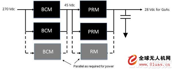
One of the applications of the 270V to 28V power supply chain is the GaAs transmitter, the block diagram of which is shown in Figure 3.

Figure 3: GaAs emitter power chain
Both payload and GaAs emitters require more than 200 watts of power. In order to meet the power demand, the BCM module and the PRM module need to be connected in parallel to the power array to increase the output power. The following paragraph talks about how to parallel BCM and PRM with current sharing capability.
BCM and PRM modules can be configured with power arrays over 1 kW.
The BCM module is an isolated unregulated DC-DC converter module that provides a high voltage input to the SELV output with a fixed ratio K factor. For this particular component (MBCM270 x450M270A00), the K factor is 1/6, so the output voltage is always 1/6 of the input voltage and the 270V input has a 45V output.
The PRM module is a regulated, non-isolated DC-DC converter module that provides regulated voltage to the load. Since the PRM output voltage can be fine-tuned, it can be adjusted down to 28V for GaAs emitters.

Figure 4: Efficiency of a GaAs emitter solution
The BCM is an isolated unregulated DC-DC converter.
The PRM is a regulated, non-isolated DC-DC converter.
As mentioned in the previous paragraph, isolation and regulation are not repeated by each stage of DC-DC conversion, or by a single DC-DC converter in the power supply chain, in order to achieve higher efficiency.
Therefore, by using BCM and PRM modules, the overall efficiency of 270V to 28V DC-DC conversion can reach 93.12%.
Parallel BCM and PRM technology:

Figure 5
While paralleling the BCM modules, it is easy to connect the inputs and outputs of each BCM module so that current sharing can be achieved by impedance matching (rather than parallel signals), as shown in Figures 5a and 5b. Parallel BCM should consider the following points.
1. Complete the input and output interconnection impedance matching by symmetric layout, as shown in Figure 5b.
2. Uniform cooling allows the temperature of a single BCM module to approach each other.
3. Each BCM module's enable/disable signal (PC pin) needs to be connected to start each module at the same time.

Figure 6: Parallel PRM
To parallel the PRM module (Figure 6), the parallel signal (PR pin) is required to achieve the current sharing of each module. At the same time, the enable/disable signal (PC pin) of the specific module needs to be connected to start simultaneously. All modules. As shown in Figure 6, a PRM module can be configured as a "master" in a power array to drive other "slave" PRM modules responsible for feedback and regulation.
Sine Amplitude Converter (SAC) topology:
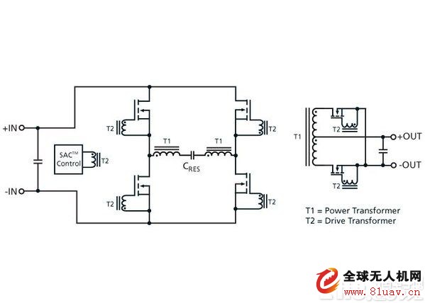
The Bus Converter Module (BCM) uses a SAC topology for superior efficiency and power density.

Figure 7: SAC Converter
The SAC topology is a dynamic, high-performance engine at the heart of the BCM module.
The SAC is a transformer-based series resonant topology that operates at a fixed frequency equal to the resonant frequency of the primary side tank circuit. The primary side switching FET is locked to the primary natural resonant frequency, switching at the zero crossing point, thereby eliminating power consumption in the switch, improving efficiency, and significantly reducing the generation of high-order noise harmonics. The primary resonant tank is a pure sinusoid (shown in Figure 7), which reduces harmonic content and provides a cleaner output noise spectrum. Due to the high operating frequency of the SAC, smaller transformers can be used to increase power density and efficiency.
A class lithium cells
Superior selection for materials & parts
Exquisite workmanshipHandicraft grade look and workmanship
High class ABS container with abrasive coating
High class brass terminals makes low internal resistance and strong discharge performance
Iron phosphate Lithium Ion Battery cathode material for lithium iron phosphate, its safety performance and cycle life is obviously can not be compared to other materials. Iron lithium battery to solve the security problem of general battery, the general battery will produce explosion in a strong collision, hidden safety problems; While the lithium iron phosphate batteries has been rigorous safety testing, even if the internal or external battery damage, also will not burn, not explode. The cycle life of the battery is normal in general about 300 times, the highest is about more than 500 times, the use of time is generally 1 to 1.5 years; While the lithium iron phosphate batteries, the cycle life of more than 2000, the standard charge (2 hours), can reach 2000 times, using the time can reach more than 4 years, it is 2 times more than the normal battery; These power battery technology index is one of the most important.
LiFePO4 Batteries for Scooters and Wheel Chairs
Scooter Battery,LiFePO4 Batteries for Scooters and Wheel Chairs,Lithium Electric Scooter,Lithium Scooter Batteries
Starlight Power Industrial Company Limited , https://www.starlite-power.com
