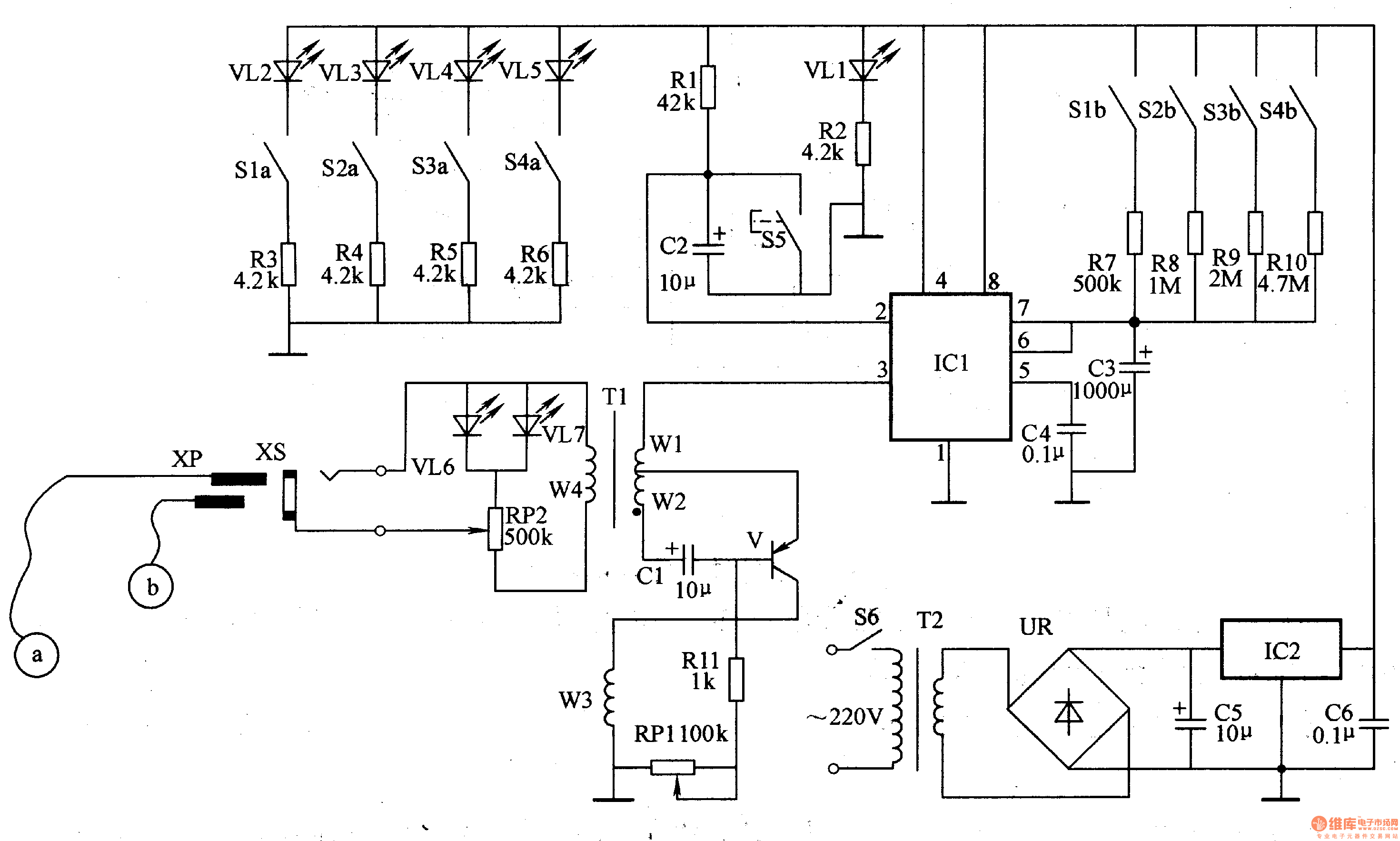
The power circuit is composed of a power switch S6, a power transformer T2, a rectifier bridge stack UR, a resistor R1, filter capacitors C5 and C6, a power source indicating LED VLl, and a three-terminal voltage regulator integrated circuit lC2.
The timing circuit is composed of resistors R1, R3-R10, LEDs VL2-VL5, capacitors C2-C4, timing switches Sl-S4, reset button 55, and time base integrated circuit IC1.
The pulse voltage generator circuit is composed of a transistor V, a resistor R11, a potentiometer RP1, RP2, a capacitor C1, a pulse transformer T1, a work indicating light emitting diode VL6, VL7, a socket XS, a plug XP, and electrodes ", b".
Turn on the power switch S6, AC 220V voltage after T2 step-down, UR rectification, C5 filtering and IC2 voltage regulation, provide +12V working voltage for the timing circuit, and VLl light.
Press S5 to make IC1's 2 pin low level, 3 pin output high level, make pulse voltage generator circuit oscillate, V intermittently conduct, generate 70V pulse voltage on T W4 winding. The pulse voltage is applied to the acupuncture points of the human body through XS, XP and electrodes a and b to assist in the treatment of some chronic diseases (such as shoulder and shoulder pain, cervical spondylosis, limb numbness, etc.).
S1 (S1a, S1b), S2 (S2a, S2b), S3 (S3a, S3b) and S4 (S4a, S3b) are four-speed timing control switches. After pressing a switch in S1-S4, the +12V voltage passes through the switch. And the series resistor charges C3, so that the voltage of pin 6 and pin 7 of IC1 keeps rising. When the voltage across C3 exceeds 8V, the circuit in ICl flips and the pin 3 outputs low level, so that the pulse voltage generator stops working. The treatment time is over. When a switch is pressed, the LED in series with the switch illuminates. For example, when S2 is pressed, VL3 is lit, and R4 and R8 are connected to the +12V power supply circuit through VL3.
Adjusting the resistance of RPl can change the frequency of oscillation of the pulse voltage generator, so that the number of pulses changes within the range of 10-120 times/min.
Adjusting the resistance of RP2 can change the intensity of the output pulse and make the output pulse voltage change between l0-70V.
Component selection
Rl-Rll selects 1/4W metal film resistor or carbon film resistor for use.
RPl selects small synthetic carbon film potentiometer or organic solid potentiometer; RP2 selects small synthetic carbon film potentiometer with switch (power switch S6).
Both Cl-C3 and C4 use aluminum electrolytic capacitors with a withstand voltage of 25V; both C5 and C6 use monolithic capacitors.
VLl-VL7 selects φ3mm high-brightness light-emitting diodes (VL6 and VL7 can also use one-end color-changing LED).
UR selects the rectifier bridge stack of lA and 5OV.
V selects S9012 or S8550 silicon PNP transistor.
ICl selects NE555 or 5G7555 type time base integrated circuit; IC2 selects 78L12 type three-terminal voltage regulator integrated circuit.
Tl uses E122 core and high-strength enameled wire winding, winding Wl-W3 with φO.25mm enameled wire wound around 60åŒ, W4 with φO.08mm enameled wire wrapped around 650åŒ; he chooses 1-3W, secondary voltage is 15-17V Power transformer.
S2-S4 uses bipolar four-position interlocking button switch; S5 selects micro-motion button.
XS selects φ3.5mm mono headphone jack; XP selects plug with XS.
The electrodes a and b were produced using a circular copper piece (outer gauze or cotton cloth) of φ5Omm and a thickness of lmm.
Conecting Terminals Without Screws
Conecting Terminals Without Screws,Cold Pressing Terminals,Low Pressure Cold Shrinkage Terminal,Cold Shrinkage Cable Terminals
Taixing Longyi Terminals Co.,Ltd. , https://www.lycopperterminals.com
